Road design
This section outlines the general procedure for designing a road from start to finish, and also provides a reference for all the functions used for road design. The road design process is very different to many of the tools that currently exist in Surpac, so it is worthwhile perusing the reference manual to find out more about it.
There are three major steps involved in road design.
- Designing the horizontal road alignment
- Designing the vertical road alignment
- Combining the two designs into a 3-dimensional road with thickness.
All of the road design functions are accessible from the Design > Road design menu.
Horizontal road design
The aim of the horizontal road design is to create a viable plan view of a road that can be used in the later stages of road design. There are two steps to the horizontal design process: designing the horizontal inflection points, and designing the horizontal alignment.
To design the horizontal inflection points, you digitise or create a segment that is a rough road centreline. Any non-collinear point in this segment is a inflection point of the road. At these inflection points, circular and transition curves will be created to produce a smooth horizontal design.
Design horizontal inflection points
There are some easily accessible functions to help with designing the horizontal inflection points, but any segment in Surpac will do. The menu used to access these functions is Design > Road design > Design horizontal inflection points.
After doing a horizontal design over a landscape, you might see something that looks a little like this.

Design horizontal Alignment
For detailed information on the specifics of the Design horizontal alignment form, please see the DESIGN HORIZONTAL ALIGNMENT reference.
The next part of the horizontal design process is to fit the circular curves and transition curves to the design. This is also the stage where the superelevation for those curves is most easily decided.
To begin designing the horizontal alignment, start the DESIGN HORIZONTAL ALIGNMENT function.
The function then prompts you to select the design segment you wish to you. After doing so, it will show the design horizontal alignment form, and number each inflection point on the design segment.
This function is used to give each inflection point a radius of curvature, transition curve length and superelevation. Any changes you make to the form will update the display, and you will be able to see the horizontal road design take shape.
Please refer to the DESIGN HORIZONTAL ALIGNMENT page for detailed information on this function.
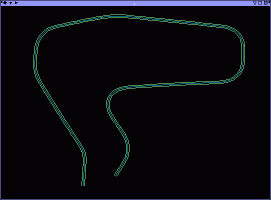
Here is a sample image of what the horizontal design may look like. As a part of the design process, D3 now contains values to indicate important parts on the design where curves begin and end.

Vertical road design
The vertical road design part of the process is focused on creating suitable gradients and curvature for the road in the vertical domain. Typically you would use an already existing surface to map the road over to create your road within your constraints.
Drape segment over DTM
The first part of the vertical design process is to create a rough vertical design from the horizontal design and the surface. We do this using the Drape segment over DTM function. To use this function, simply select your horizontal road design, and then choose the layer that the DTM exists in, and the segment will be changed to match the surface of the DTM. For more detailed information on how to use this function, please see SEGMENT OVER DTM.
A useful hint is to use the Create road outline function on the road centreline several times over different widths before you drape the segment over the DTM. This allows you to have several moving 'sections' of the terrain the road will be on, giving you a good picture of the changing surface when working in the vertical design domain.
Create longitudinal profile
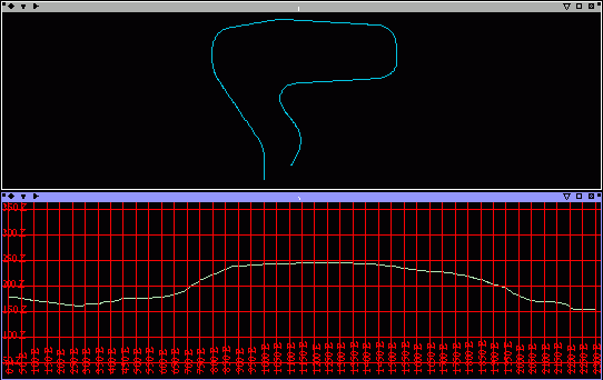
Use this function to take your newly draped road centreline and 'unwrap' it so we can plot the road height by its chainage in 2 dimensions. This lets you visualise and work with your road in the vertical design domain without having to work with the horizontal domain in 3 dimensions at the same time.
This function will look at the D2 fields for chainage values to use if you want it to. Note that it can also work with segments that do not have chainages, and in that case it will just interpolate using 2D line distances.
Here is an example of a longitudinal profile from the horizontal design and surface shown above:
Design vertical inflection points
This step is the same in concept to the design horizontal inflection points. The goal here is to create a good vertical design to then create the vertical curves with. How you arrive at this final design is up to your constraints and requirements for your project. Ensuring that all your roads have certain grades is a common constraint, as is keeping reasonably close to the original terrain to minimise waste.
The only requirement is that you finish up with a segment that has the same length in the X direction as the chainage of the road you will be applying the design to.
Design vertical alignment
This function is similar to the "Design horizontal alignment". It takes a segment that is the vertical design, and then creates vertical curves based on a curve length. The chief difference here is that it uses parabolas to define the curves, and the curve length is measured just along the X axis, so it is much easier to visualise and manipulate than the horizontal curves.
Please note that things like road and vehicle visibility are not handled by this road design process, so if your design requirements, you will need to factor in these calculations manually.
Apply longitudinal profile
Use this function to take your new vertical design, and apply it back to your horizontal design, to produce a road centreline in 3 dimension, ready for further use. It will take the profile and apply the Z position of each of points in the segment, and either add or move points in the horizontal design at the correct chainage in the horizontal design. Please see the APPLY LONGITUDINAL PROFILE function for more details.
Finishing off
Create road outline
This function takes any segment, and creates a road outline at a specified width each for the left and right side. This function also takes into account any superelevation present in D4, and will use the chainage values in D2 for interpolation.
To run this function: Choose Design > Road design > Create road outline, or...
This is quite a flexible function, as it can apply variable road widths over the length segment, with the left and right road widths optionally in D6 and D7 respectively.