


Design Vertical Alignment
This function is used to generate a curved vertical design from a vertical design containing inflection points. This input vertical design is typically derived from a longitudinal profile created using Create longitudinal profile.
To run this function: Choose Design > Road design > Design vertical alignment, or...
Here is a very simple example of a vertical design segment.
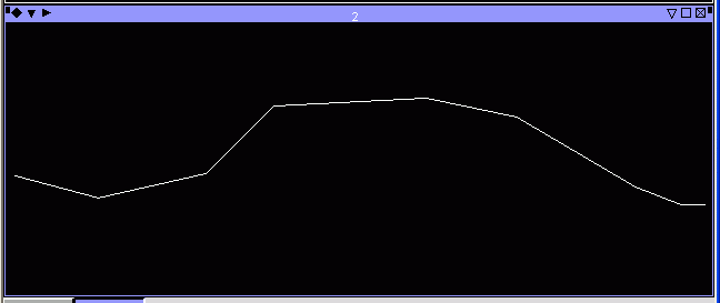
The first thing that happens is you are asked to select your vertical design segment. Click on the segment to display the Design vertical curve form, shown below:
Fields on the Design vertical curve form
| Output string | The string that the vertical curves will be created in. This must be filled in to have the inflection point numbers displayed. |
| Chainage interval | The minimum interval between each point on the vertical curves. Ideally, this should be the same chainage used to create the horizontal design. An example value is 25.00 |
Note: In general you should create the vertical design segment so that the two end points of the vertical design segment exactly match the end points of the longitudinal profile. Failure to do this may result in erroneous points being added to the end of the final result centreline. If you wish to smooth the whole length of the original horizontal design you will need to make sure that the first and last points in the vertical design segment and the longitudinal profile segment exactly match. You can do this by either using the 'snap to point' mode when digitising the vertical design segment, or you can use POINT MOVE in the 'snap to point' mode to move the start and end points of the existing vertical design segment to exactly match the start and end points of the longitudinal profile. Surpac checks for this matching of the end points and displays a warning if this condition is not satisfied.
Road Design details
This table displays each inflection point in the vertical design. The numbers for each row match up with the numbers shown next to each inflection point in the graphics viewport. Below is an explanation of each column shown here
| IP chainage | This is the chainage along the road at each inflection point. This is useful to know, as it easily shows how far apart each inflection point is, which in turn limits the curve length available to you. An example value is 278.01. |
| Grade in | This is the grade of the road segment coming into this inflection point. An example value is -6.53. |
| Grade out | This is the grade of the road segment going out from this inflection point. An example value is 5.85. |
| Type | Indicates what type of vertical inflection this is. It can be either 'Hollow' or 'Crest' |
| Status | Shows if the current road design is valid or not at the current inflection point. When the curve length is modified, this may change to 'Invalid' to show that the curve length has exceeded an acceptable level. |
| Curve length | The length of the curve to create at the inflection point. This is measured in the chainage along the x axis. As this is changed, the graphics viewport will be updated to show the new design. An example value is 150. |
After clicking Apply, the vertical design will be created in the given string number, and you will be ready to continue on with the road design.