


New ramp
You can use this function to define a ramp for a selected segment so that the segment and string expansion functions available on the Pit design menu will create the shape of the ramp when the segment is expanded.
To run this function: Choose Design > Pit design > New ramp, or...
 Note: The UNDO function does not work with DEFINE NEW RAMP.
To remove a ramp that you have created, use EDIT RAMP DEFINITIONS to delete the ramp.
Note: The UNDO function does not work with DEFINE NEW RAMP.
To remove a ramp that you have created, use EDIT RAMP DEFINITIONS to delete the ramp.
To run this function: Choose Design > Pit design > New ramp.
When you run the function you will see two messages:
Select the first ramp point: Use the mouse to select the point which defines one side of the ramp.Select the second ramp point: Use the mouse to select the point which defines the other side of the ramp.
You should select two adjacent points, on the same segment, which are spaced apart by a distance which is approximately equal to the width of the ramp you want to create. The order that you select the points is not important. After you have selected the ramp points, the Define a new ramp form is displayed.
Fields on the Define a new ramp form
| Field | Description |
|---|---|
|
Ramp name |
The name of the ramp. By naming the ramp, you make it easy to edit the properties of the ramp, such as width and gradient when using RAMPS EDIT. This is especially useful when you are creating more than one ramp for a segment. |
|
Ramp string |
The ramp is represented by two segments, one for each side of the ramp. Enter the string number for these segments. You should choose a string number which is not already in use nor which is likely to be used by the expansion functions because each time these functions are used they create a new string by incrementing the string number of the selected segment. It is easier to manage the ramp edge segments for plotting if you choose a string number that will remain unique. |
|
Ramp type |
The type of ramp which will be created. Choices are:
|
|
Ramp width |
The width required for the ramp. This field has a default value, rounded to the nearest unit, of the distance between the two selected points. The ramp width can help you verify whether the correct points have been selected. |
|
Ramp gradient 1: |
The gradient required for the ramp. The gradient is defined as a ratio. For example, if you enter a value of 10, you will produce a ramp with a gradient of 1 in 10, or 10%. Note: The following ramp design parameters relating to gradient and berm width are only relevant for circular ramps. They become inactive when Ramp type is 'all cut' because they have no significance for 'all cut' ramps. |
|
Gradient method |
For circular ramps, you can use several different methods to calculate the gradient of the ramp. This is required only when the ramp has relatively tight corners which result in significantly different lengths along one side of the ramp in contrast to the other side of the ramp. Choices are:
|
|
Berm crossing method |
When a circular ramp crosses a berm in the pit design you can choose to create the ramp strings so that the berm meets the ramp on:
The method of berm crossing which you should choose depends on local conditions and design requirements. Choices are:
|
|
Berm taper distance |
Regardless of the berm crossing method, you must define a distance to taper the ramp geometry neatly when berms are inserted into the design. The berm taper distance defines how far either side of the berm crossing the ramp geometry is modified to create acceptable ramp geometry. It is important that the berm taper distance is appropriate for the design conditions. The berm taper distance must not be greater than the distance between successive crossings of the ramp by the pit outline segments otherwise the adjustments made at one berm crossing will be unduly influenced by the adjustments made at the next or previous berm crossing. |
| Define the switchback characteristics | |
| Switchback angle | The angle, in decimal degrees, that the switchback will turn. |
| Switchback inner radius | The radius of the inner part of the curve of the switchback. |
If the ramp is a circular ramp, no more input is required. If the ramp is an 'all cut' ramp, the following message is displayed:
Select the All Cut ramp centre line string
In Graphics, select the segment which will represent the centre line of the all cut ramp. When you select the segment, consider the following guidelines:
- The centre line segment must intersect with the line between the two selected points of the ramp edge.
- The start of the centre line segment must be 'near' the line between the two selected ramp edge points. You can easily determine where the start of the centre line is by drawing the segment label for the centre line segment. This label is drawn at the start of the segment. If the label is drawn at the end of the centre line segment which is furthest from the line between the two ramp edge points, you should use the SEGMENT REVERSE function to make the segment start in the correct location.
- For best results, the point at which the centre line segment intersects with the line between the two selected ramp edge points should be approximately halfway between the two selected points of the ramp edge.
The following diagram may help you understand these conditions. The line on the left is the centre line segment. The line on the right is the intersecting line which intersects between the two selected ramp points.
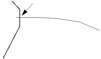
You can extend the segment of the centre line of the ramp at any time during the design process by using any of the graphics editing or digitising functions. Generally, the ramp centre line segment is stored in a different layer to the pit design you are creating. This is because you will ultimately create a DTM from the pit design and the centre line segment of the ramp cannot be included in this DTM because it has no meaningful elevations.
Output
The ramp data is attached to the segment. When you use the string and segment expansion functions on the Pit design menu, Surpac uses the ramp data to create the strings of the ramp edge and to alter the shape of the segments as the design progresses from one level to the next.
Warnings
The ramp points MUST be adjacent
This message is displayed if the two points you have selected are not immediately adjacent to each other. This can sometimes be difficult if the segment contains more than one point at exactly the same X,Y,Z position.
After this message is displayed you are prompted to reselect the first ramp point.
Ramp design considerations
- When you design pits and dumps with ramps, some editing functions can cause the ramp data to be lost. If you lose ramp data, you have to redefine the ramps to design the next level of the pit. During the design process, you should be careful when using SEGMENT BREAK and SEGMENT JOIN. These functions result in existing segments being destroyed and replaced with new segments. Because the ramp data is attached to the segment, any action which results in a segment being destroyed will result in the loss of the ramp data.
- Know and remember the positions (X, Y, Z values) of the ramp edge points after the string and segment expansion functions are applied. If you edit the points of the ramp edge and move them to a new location, you might have to redefine the ramp edge points. If this occurs, the following message is displayed:
- When designing an all cut ramp, the ramp centre line segment must be long enough for the design, otherwise the ramp will end prematurely. If this occurs, undo the last expansion and extend the centre line segment of the ramp and then run the segment expansion function again.
The 'ramp name' ramp edge points have been moved or deleted.
				They must be re-selected to continue.
You must then select the ramp edge points as you did when the ramp was originally defined. Use the mouse to select the ramp edge points as you did originally and the design will then proceed.