


Zone thickness and depth
With this function you can extract the depth to the top or bottom of a geological zone for selected drill holes in the database. This can be particularly useful when dealing with consistent strata such as lateritic deposits or coal seams, since the output can be used to form a DTM and then contours can be extracted and volumes calculated.
To run this function: Choose Database > Extract > Zone thickness and depth, or...
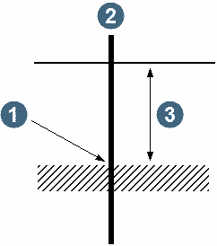
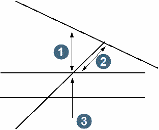
The depth is calculated as the length between the top of the hole, and the top or bottom of the specified geological zone. Care should be taken when using this function where the drill holes are not vertical or the required zone is steeply dipping, since the depth that is calculated is an apparent depth rather than a true depth as shown in diagram (b) below. However, the coordinates stored in the y, x and z fields will always represent the true position of the top or bottom of the zone and so can be used to model the zone with DTMs. The following diagram shows a situation where the correct depth is reported.
|
1. y, x, z coordinates 2. drill hole 3. depth |
The following diagram shows a situation where the depth that is reported is not the true depth.
|
1. true depth 2. reported depth 3. y, x, z coordinate |
Fields on the Zone thickness and depth form.
Define the string file to create
Location and ID number
Enter the Location name and ID number of the string file to be created.
String
Enter the String number to store the points containing the zone thickness and depth information.
No zone string
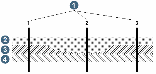
Enter the string number which will contain points for those drill holes that do not have the zone of interest. These holes will have an output thickness of zero, which could be useful for producing DTM's and contours of thickness. The reason that points are created for these drill holes can best be illustrated in the following example:
|
1. drill holes 2. MS 3. BD 4. SH |
If a value is not calculated for every hole in the example above, only drill holes 1 and 3 will have a thickness value written out to a string file for zone BD. When a DTM is formed to extract the thickness contours from, a triangle will be formed from hole 1 to hole 3 thus interpolating a thickness of BD for hole 2.
If you do not require the drill holes which do not intersect the zone of interest then you may prefer to enter 0 (zero) for the No Zone String. This will prevent these drill holes from appearing in the string file.
Which zone selection method
Enter the method that you wish to use for defining the geological zone of interest:
- MULTIPLE ZONES, define the zone by entering one or more geology codes.
- ZONE FROM TO, define the zone by entering the code at the top of the interval and the code at the bottom of the interval.
Use True Thickness
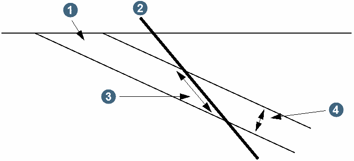
To calculate the true thickness of a geological zone, the dip and dip bearing of the zone are required.
To estimate the error in the computed true thickness, the errors associated with the dip and dip bearing angles must also be entered. These are important as depending on the geometry of the drill hole and zone, small measurement error in these angles can lead to large errors in the true thickness.
|
1. geological zone 2. drill hole 3. reported length 4. true thickness |
There are three possible ways to enter the orientation of the geological zone.
- one average value that applies to all zones in all drill holes
- in the form of strings in a 'dips' file
- in a points table in the database
All angles must be given in degrees, and only one of these can be used at a time.
Required co-ordinate position
This option allows you to determine the coordinates of the points in the result file with respect to the top, middle or bottom of the zone of interest. If you enter:
- top, the coordinates will be at the top of the zone of interest, or
- middle, the coordinates will be at the middle of the zone of interest, or
- bottom, the coordinates will be at the bottom of the zone of interest, or
Complete the ZONE THICKNESS AND DEPTH form and choose Apply.
Depending on the zone selection method you chose at the Define the zone selection method prompt (Multiple zones or Zone from to), one of two forms is displayed to permit you to define the geological selection criteria.
If you did not request true thickness to be calculated the DEFINE QUERY CONSTRAINTS form is displayed.
Complete the SELECT CONSTRAINTS FOR FIELDS form and choose Apply to commence processing and return you to the EXTRACTING POINTS submenu.
If you chose `Y' at the Use True Thickness prompt on the THICKNESS OF ZONE form, the following CALCULATE TRUE THICKNESS form is displayed.
Calculate true thickness form
This form allows you to choose the orientation of the geological zone. Enter `Y' to one of the following.
By average dip and bearing (Y/N)
One dip and one bearing angle apply to all holes and all zones. In addition, error values must be specified for these two angles.
From slope files (Y/N)
If you enter `Y', then you are required to enter the dip string file Location and ID. The dip string file may contain any number of strings, each of which have any number of segments. Each segment of each string must have the dip angle in the D1 field, and the dip bearing in the D2 field. Error angles must be in D3 and D4.
When a zone is identified and its northing and easting computed, the dip strings are examined to find the segment containing the point. The angles supplied with that string are then used in the true thickness calculation. The extent of these strings must be large enough to include all drill holes.
From database fields (Y/N)
Enter `Y' to display two more forms to enable you to enter the name of the dip and bearing table and dip and dip direction field names.
The SELECT THE DIP AND BEARING TABLE TO PROCESS form requests the name of the table which contains the dip and dip direction fields.
Note: The dip and dip direction are attributes which are measured at a point down the drill hole. Therefore, these attributes must be stored in a point table. That is, the table must have hole_id and depth_to as the unique index.
The DIP AND DIP DIRECTION FIELD NAMES form requests the field names for the Dip and Dip Direction fields. The error in the dip and bearing angle is determined from the internal spread in values in the table. No error values need be supplied.
Complete the CALCULATE TRUE THICKNESS form and choose Apply to display the DEFINE QUERY CONSTRAINTS form.
Complete the DEFINE QUERY CONSTRAINTS form and choose Apply to commence processing and return you to the EXTRACTING POINTS submenu.
Result
The output from this function will be a string file containing:
- A point for each drill hole which intersected the zone of interest. These points will be in the specified string number.
- A point for each drill hole which did not intersect the zone of interest in the No Zone String. Remember that you can use string zero to exclude these points from the result.
Various items of data are saved in the description fields as described in the table below.
| Field | Contents |
|---|---|
| D1 | Hole ID |
| D2 | Total length of the requested zone. This length will be adjusted to a true thickness if this has been requested. |
| D3 | Total length of any included waste material between the top and bottom of the zone of interest. Waste material is that material between the top and bottom of the zone of interest which has a rock code other than the code for the zone of interest. This thickness will be adjusted to a true thickness if this has been requested. |
| D4 | Depth to the top of the zone of interest |
| D5 | Depth to the bottom of the zone of interest. |
| D6 | This is the number of discrete contiguous zones of the specified rock type between the top and bottom of the zone of interest. If there are no sections of intervening waste material then this will be 1. If there is one section of intervening waste material this will be 2, etc. |
| D7 | This is the vertical thickness of the zone of interest. This is only reported if you specify to report true thickness in D3. Note that a value of -1 will be reported for a vertical orebody. |
| D8 | This is the horizontal thickness of the zone of interest, measured in the dip direction. This is only reported if you specify to report true thickness in D3. Note that a value of -1 will be reported for a horizontal orebody. |