


Composite by Grade
With this function you can produce composite samples based on grade constraints and a minimum composite width. Internal dilution, that is, intervening material that is less than the minimum acceptable grade for the composite, can optionally be included provided the width of the intervening material does not exceed a user specified amount. This function also permits you to calculate the composite samples by using true thickness rather than apparent thickness if required. The results are effectively bulked samples that will not necessarily be of equal length and so should not be used as input for statistical or geostatistical studies.
The resulting grades/qualities can be weighted by length alone or optionally by other fields in the table containing the sample data. This is useful if it is necessary to weight by specific gravity or recovery.
To run this function: Choose Database > Composite > By grade constraints, or...
Compositing begins at the first ore sample and continues until the addition of a sample would cause the composite to fall below ore grade or result in the inclusion of a waste interval wider than the specified maximum dilution. Any waste added before the composite end is clipped off.
The compositing by grade process involves three passes over the data:
- Pass 1: Forward pass - composites samples downhole.
- Pass 2: Reverse pass - composites samples included in results from pass 1, but in reverse. If a composite does not hold in reverse, it is broken.
- Pass 3: Forward pass - calculates composites downhole, using results from 1 and 2 to determine which samples are to be included.
Selection by geology or hole depth causes steps 1. to 3. to be run over each of the specified geology or depth intervals individually.
There are two options that control how negative or missing assays are handled. These are the options of breaking on missing or negative master assays and diluting on missing or negative assays.
The main use of this function will be to create a string file of high grade intercepts for plotting purposes. The top and bottom of each composite is saved to a string file so that Digital Terrain Models may be formed of the footwall and hanging wall of the high grade structure.
Fields on the Composite by grade form.
Composite by grade form
Table name
Enter the name of the table containing the sample data which will be used for defining the sample fields which are to be extracted.
Sample field, Field name
Enter the name of each of the sample fields which are to be included in the string file containing the composite samples.
Weighting fields - Field Name, Default
If required, the calculation of the grades/qualities in the composite samples may be weighted by some other field/s in the sample table in addition to the length weighting which is already performed.
Typically, additional weighting fields used would be specific gravity and/or recovery. A maximum of 5 additional weighting fields may be used. Enter the field name/s which are to be used to provide the additional weighting criteria for the creation of the composite intervals.
Under some circumstances it is likely that no values may be available for the weighting field for some samples. The Default input field permits a reasonable default value to be defined to cover this circumstance.
The default value is used in preference to the stored value in the table when either a null value is present or when the value present is less than zero.
Minimum grade
Enter the minimum acceptable grade to be used for creating the composite intervals. This value is used for the first field defined in the Sample fields input table.
Minimum composite width
Enter the minimum width for the composites to be generated.
Maximum internal dilution
Enter the maximum width for any internal low grade material that will be allowed to be included in the composite.
Use true thickness
The Minimum composite width and Maximum internal dilution parameters and the length calculations performed on the raw sample data to create the composite sample intervals can done either as apparent or true widths. If the checkbox is unticked all values are considered as apparent widths. If the checkbox is ticked all values are considered to be true widths.
If you tick the checkbox to perform true width calculations the Calculate True Thickness form will be displayed to define the method of determining the dip and dip direction for the mineralised zone.
True thickness calculations can be complex to understand because of the different factors that are considered when performing the calculation. The method used to calculate the true thickness is:
- For each sample obtained from the interval table for which the composites are being calculated the true width of the sample is calculated by using the dip and direction of the borehole trace AND the dip and dip direction of the mineralised zone at the mid point of the sample.
- The true width value for individual samples, and for the gaps in sampling, are added together and compared with the minimum width and maximum dilution values entered. Thus these control parameters are interpreted as being true width values.
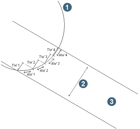
Calculating true widths for individual samples and adding them together gives results that become progressively less accurate as the variation of the dip and azimuth of the drillhole and the dip and dip direction of the mineralised zone increase over the length of the composite interval that is created. The most likely outcome of this is that the true width reported for the composite interval may be greater than what you might expect it to be. The diagram below which has extreme, and completely unrealistic, curvature demonstrates this quite clearly. To be confident that the results are meaningful for your circumstances you should examine the variation of the borehole path and the orientation of the mineralised zone to ensure that the variations are not so extreme that the results will be meaningless.
|
1. drill hole collar 2. true width 3. mineralised zone |
In the diagram above there are 4 samples in the mineralised zone with the apparent width of the samples denoted as AW1, AW2, AW3 and AW4. Each of these samples has a true width, nominally TW1, TW2, TW3 and TW4. Under certain circumstances, where significant variation in the angle between the orebody dip and drillhole orientation exists, the sum of the true widths for the samples of interest may be greater than the true width of the zone of interest. It is this geometric peculiarity that you must be alert for.
Break on blank or negative master assay
- Y, causes a break in the composite if a blank (missing) or negative master assay is encountered.
- N, the master assay is treated as described below.
Dilute blank or negative samples
- Y, blank (missing) or negative samples are diluted as if equal to zero. For example, 9, -1, 9 would result in a composite value of 6, i.e. ((9+0+9)/3).
- N, blank (missing) intervals and intervals with a negative assay are ignored in the calculation of composite values. For example, 9,-1,9 would result in a composite value of 9 ((9+9)/2).
Select by hole depth
Enter `N' if bulking is to be carried out for the entire hole depth.
Enter `Y' if you wish to restrict the bulking of grades by hole depth.
If you enter 'Y' then you must enter the upper and lower limiting depths to be used for all holes at the Upper and Lower prompts on this form.
For example, if you wish to generate composite values for the top two metres of all holes in the database to use as soil samples. To do this, you could specify a composite width of zero, an internal dilution of zero and a zero grade with a depth from zero to 2.
Define the zone selection method
You can restrict the bulking of grades to be within particular geological zones by choosing one of the following:
- NO SELECTION, do not select by geology.
- MULTIPLE ZONES, define the zone by entering one or more geology codes.
- ZONE FROM TO, define the zone as being from the top or bottom of one geology code to the top or bottom of another.
Sample co-ordinate point
The composite interval may be represented in the resultant string file as a single point at either the top, middle or bottom of the composite interval, or by a string segment representing a line drawn from the top to the bottom of the composite interval.
Choose `top', `middle', `bottom' or `segment' to create the required result.
Define the string file to create
The Location and ID number of the string file to be created need to be entered, along with a string number to store the resulting composites.
Define code for composite intervals
Each drillhole interval produced by this function can be coded and output for later processing, interaction or reporting. The intervals can be saved to a database table for later work or graphics for immediate interaction with interactive compositing.
Write codes to
Select one of:
- database, to save the coded intervals to a database table.
- graphics, to save the coded intervals to graphics for interactive compositing.
- leave the field blank, to not save coded intervals.
Table name
Select the database table into which the current composite intervals will be written. We recommend that if you plan to save the composites to the database then you should create a separate table for storing the composite details. The reason for this is that the since these composites are the result of interpretation it is better to not mix them with actual measurements of the drill hole from the logging operation.
Certain actions are performed when saving the composite intervals to the database table to ensure that the integrity of data which may already exist in the table is maintained. The actions taken will depend upon how many existing samples for the drillhole exist within the depth_from and depth_to values for each composite interval. There are a number of different cases to be explained. Each of these cases are described in detail below:
- No existing samples overlap with the new composite interval. In this case one new record is entered into the table with the depth_from and depth_to values of the composite interval and the composite code is saved to the nominated field. Any other fields in the table will have blanks or zeros stored for character and numeric fields respectively. Because of this you should ensure that the fields in the table will permit the entry of nulls. When the new samples are created, the only field which will have a value defined is the field to which the composite code is being saved.
- Existing samples overlap the new composite interval. Any existing samples which overlap with the new composite intervals will be split so that the existing intervals no longer overlap with the new intervals. In addition a new record will be inserted if an overlap between the existing and new intervals exists at the top of the interval, and a new record will also be inserted if an overlap between the existing and new intervals exists at the bottom of the interval. These new intervals will have values saved to any optional fields to ensure that the integrity and contiguity of any existing intervals is maintained.
-
Existing samples contained within the new composite interval.
Any existing samples which are completely included by a composite interval will have the composite code stored in the appropriate field and no further changes will be made to the existing sample.
Field name
Select the field in the table to which the composite codes will be written.
Interval code
The code to use for output intervals.
Complete the COMPOSITE BY GRADE form and choose Apply. If the Use true thickness checkbox has been ticked the Calculate True thickness form will be displayed to define the true thickness parameters.
Two different methods of defining the dip and dip direction of the mineralised zone may be used. These are:
- By using average values for the dip and dip direction. You would use average values when the dip and dip direction are reasonable consistent over the area of interest or when the dip and dip direction are only approximate and you want an approximate idea of the true thickness. When using this method you must enter the dip and dip direction in decimal degrees.
-
By using values for the dip and dip direction defined by a number of closed segments where the region inside each closed segment defined a specific dip and dip direction. In this way you can model some variation in orebody dip.
This method requires you to define the dip string file(s) which may contain any number of strings, each of which have any number of segments. Each segment of each string must have the dip angle in the D1 field, and the dip bearing in the D2 field. Error angles must be in D3 and D4. The dip and dip direction values must be specified in decimal degrees.
When a zone is identified and its northing and easting computed, the dip strings are examined to find the segment containing the point. The angles supplied with that string are then used in the true thickness calculation. The extent of these strings must be large enough to include all drill holes.
The error values may be ignored as they are not used in calculating the result at this time.
Depending on the zone selection method you chose at the Define the zone selection method prompt (Multiple zones or Zone from to), one of two forms is displayed to permit you to define the geological selection criteria.
Complete the zone selection forms and choose Applyto display the SELECT CONSTRAINTS FOR FIELDS form.
Complete the DEFINE QUERY CONSTRAINTS form and choose Apply to begin the compositing process.
Messages
Upon completion of processing the name of the output string file which is created and the number of holes which have been processed will be displayed in the message window.
Result
The output from Compositing by Grade is a string file containing:
- The string number defined on the COMPOSITE BY GRADE form will contain the composites found with the coordinates which represent the position at the top, middle or bottom of the composite interval. The first description field will contain the composite grade of the master sample, with the other sample element composites stored in subsequent D fields. The last two description fields will contain the length of the composite and the hole identifier.
- If you requested that the result was to be a segment for each composite sample interval, then each composite interval is represented by a line segment of two points with the first point being the top of the interval and the second point being the bottom of the interval. The contents of the various description fields are the same as above.
The description field of the output file contains the following information:
| Field | Contents |
|---|---|
| D1 | The composited grade for the first specified sample field. The second and subsequent description fields will contain the composite grades for the second and subsequent sample fields if more than one sample field is extracted. |
| D2 | Composite sample length If only one sample field is extracted the composite sample length will be in D2. The composite sample length is actually found in the first description field after the last sample field which was extracted. If true thickness calculations are being performed the D2 field will be true thickness. |
| D3 | Hole ID If only one sample field is extracted the Hole ID will be in D3. The HOLE ID value is actually found in the description field after the composite sample length. |
| D4 | Depth from If only one sample field is extracted the depth_from will be in D4. The depth_from value is actually found in the description field after the Hole ID. |
| D5 | Depth to If only one sample field is extracted the depth_to will be in D5. The depth_from value will always be found in the field after the depth_from field. |
| D6 | If only one sample field is extracted the total weight will be in D6. The total weight will be found in the field after the depth_to field. This field only exists if optional weighting fields are used. This field will contain the total weighting value of all samples used in the composite. If weighting by specific gravity, dividing this value by the composite length will give the length weighted specific gravity. |
Further Processing
The resulting string file can be used to produce plots of the composited data, either on the screen using GRAPHICS, or hard copy plots using PLOTTING.
Composite by Geology
With this function you can produce composite samples based on geological constraints. The results are effectively bulked samples that will not necessarily be of equal length and so should usually not be used as input for statistical or geostatistical studies. The main use of this function will be to create a string file of geologically constrained composites for plotting purposes.
The resulting grades/qualities can be weighted by length alone or optionally by other fields in the table containing the sample data. This is useful if it is necessary to weight by specific gravity or recovery.
To run this function: Choose Database > Composite > By geological constraints, or...
Fields on the COMPOSITE BY GEOLOGY form.
Define the string file to create
The Location name and ID number of the string file to be created need to be entered, along with a string number to store the resulting composites.
No zone string
A value is output for every hole that meets the hole selection criteria, even if the other selection criteria are not met. Enter the string number for those holes that do not meet the other selection criteria. The points representing these holes will contain a blank composite thickness and a blank composite grade. This could be useful, particularly for producing DTMs and contours of composite thickness.
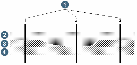
The reason that it may be important to calculate a value for every hole can best be illustrated in the following example.
|
1. drill holes 2. MS 3. BD 4. SH |
If a value is not calculated for every hole in the example above, only drill holes 1 and 3 will have a thickness value written out to a string file for zone BD. When a DTM is formed to extract the thickness contours from, a triangle will be formed from hole 1 to hole 3 thus interpolating a thickness of BD for hole 2.
If you do not require the drill holes which do not intersect the zone of interest then you may prefer to enter 0 (zero) for the No Zone String. This will prevent these drill holes from appearing in the string file.
No samples string
Some drill holes may be logged as intersecting the geological zone of interest but may not have the results for any samples recorded in the database. Generally it is preferable to treat such holes differently from other holes.
Holes which are in this category can be output to a different string number by entering the appropriate string number here. If these holes are not required enter 0 (zero) for the string number.
Define the zone selection method
You can restrict the bulking of grades to be within particular geological zones by choosing one of the following:
- NO SELECTION, do not select by geology.
- MULTIPLE ZONES, define the zone by entering one or more geology codes.
- ZONE FROM TO, define the zone as being from the top or bottom of one geology code to the top or bottom of another.
Dilute blank or negative samples
In many cases gaps may exist in the samples down a drill hole. If this situation exists in your data then you must decide how you want it to be treated. You may treat this situation by either:
- Respond with "Y" to treat missing samples as if the sample value were ZERO. This has the effect of diluting the average value of the samples which are composited into a single point value.
- Respond with "N" to completely ignore any missing samples. This has the effect of reporting a composite value which only includes the sampled sections of the drill hole.
Sample co-ordinate point
The composite interval may be represented in the resultant string file as a single point at either the top, middle or bottom of the composite interval, or by a string segment representing a line drawn from the top to the bottom of the composite interval.
Choose `top', `middle', `bottom' or `segment' to create the required result.
Table name
Enter the name of the table containing the sample data which will be used for defining the sample fields which are to be extracted.
Fields to be composited, Field name
Enter the name of each of the sample fields which are to be included in the string file containing the composite samples.
Optional weighting fields - Field Name, Default
If required, the calculation of the grades/qualities in the composite samples may be weighted by some other field/s in the sample table in addition to the length weighting which is already performed.
Typically, additional weighting fields used would be specific gravity and/or recovery. A maximum of 5 additional weighting fields may be used. Enter the field name/s which are to be used to provide the additional weighting criteria for the creation of the composite intervals.
Under some circumstances it is likely that no values may be available for the weighting field for some samples. The Default input field permits a reasonable default value to be defined to cover this circumstance.
The default value is used in preference to the stored value in the table when either a null value is present or when the value present is less than zero.
Define code for composite intervals
Each drillhole interval produced by this function can be coded and output for later processing, interaction or reporting. The intervals can be saved to a database table for later work or graphics for immediate interaction with interactive compositing.
Write codes to
Select one of:
- database, to save the coded intervals to a database table.
- graphics, to save the coded intervals to graphics for interactive compositing.
- leave the field blank, to not save coded intervals.
Table name
Select the database table into which the current composite intervals will be written. We recommend that if you plan to save the composites to the database then you should create a separate table for storing the composite details. The reason for this is that the since these composites are the result of interpretation it is better to not mix them with actual measurements of the drill hole from the logging operation.
Certain actions are performed when saving the composite intervals to the database table to ensure that the integrity of data which may already exist in the table is maintained. The actions taken will depend upon how many existing samples for the drillhole exist within the depth_from and depth_to values for each composite interval. There are a number of different cases to be explained. Each of these cases are described in detail below:
-
No existing samples overlap with the new composite interval.
In this case one new record is entered into the table with the depth_from and depth_to values of the composite interval and the composite code is saved to the nominated field. Any other fields in the table will have blanks or zeros stored for character and numeric fields respectively. Because of this you should ensure that the fields in the table will permit the entry of nulls. When the new samples are created, the only field which will have a value defined is the field to which the composite code is being saved.
-
Existing samples overlap the new composite interval.
Any existing samples which overlap with the new composite intervals will be split so that the existing intervals no longer overlap with the new intervals. In addition a new record will be inserted if an overlap between the existing and new intervals exists at the top of the interval, and a new record will also be inserted if an overlap between the existing and new intervals exists at the bottom of the interval. These new intervals will have values saved to any optional fields to ensure that the integrity and contiguity of any existing intervals is maintained.
-
Existing samples contained within the new composite interval.
Any existing samples which are completely included by a composite interval will have the composite code stored in the appropriate field and no further changes will be made to the existing sample.
Field name
Select the field in the table to which the composite codes will be written.
Interval code
The code to use for output intervals.
Complete the COMPOSITE BY GEOLOGY form and choose Apply. Depending on the zone selection method you chose at the Define the zone selection method prompt (Multiple zones or Zone from to), one of two forms is displayed.
Complete the zone selection forms and choose Apply to display the SELECT CONSTRAINTS FOR FIELDS form.
Complete the DEFINE QUERY CONSTRAINTS form and choose Apply to begin the compositing process.
Messages
Upon completion, the name of the output string file which is created and the number of holes which have been processed will be displayed in the message window.
Result
The string file created by this function will contain a string where the points represent the position at the top, middle or bottom of the composite interval as shown below. The D1, D2, etc. fields will have the composited grade (weighted by sample length) for each of the sample fields which were extracted during the compositing process.
The last description field will contain the hole ID while the second last description field contains the length of the composite sample.
cmp ,10-Jan-97 ,Composite of assays by grade , 0, 0.000, 0.000, 0.000, 0.000, 0.000, 0.000 1, 7050.858, 2375.486, 107.343, 5.5163,5.0717,10.310,RC001,48.340,58.650,925.000 1, 7053.000, 2420.092, 121.160, 10.5788,8.8925,23.060,RC002,18.670,56.500,130.742 1, 7052.000, 2467.387, 123.454, 4.6376,3.2554,26.870,RC003,21.340,48.210,84.425 1, 7053.500, 2510.075, 140.107, 7.1802,5.8927,4.560,RC004,13.670,18.230,27.854 |
If you requested the result was to be a segment for each composite sample interval, the result will appear similar to the example shown below. Each composite interval is represented by a line segment of 2 points with the first point being at the top of the interval and the second point being at the bottom of the interval. The contents of the various description fields are the same as in the example above.
cmp ,10-Jan-97 ,Composite of assays , 0, 0.000, 0.000, 0.000, 0.000, 0.000, 0.000 1, 7050.882, 2372.959, 111.836, 5.5163,5.0717,10.310,RC001,48.340,58.650,925.000 1, 7050.832, 2378.007, 102.846, 5.5163,5.0717,10.310,RC001,48.340,58.650,925.000 0, 0.000, 0.000, 0.000, 1, 7053.000, 2410.635, 137.541, 10.5788,8.8925,23.060,RC002,18.670,56.500,130.742 1, 7053.000, 2429.550, 104.780, 10.5788,8.8925,23.060,RC002,18.670,56.500,130.742 0, 0.000, 0.000, 0.000, 1, 7052.000, 2460.670, 135.089, 4.6376,3.2554,26.870,RC003,21.340,48.210,84.425 1, 7052.000, 2474.105, 111.819, 4.6376,3.2554,26.870,RC003,21.340,48.210,84.425 0, 0.000, 0.000, 0.000, |
The description field of the output file contains the following information:
| Field | Contents |
|---|---|
| D1 | The composited grade for the first specified sample field. The second and subsequent description fields will contain the composite grades for the second and subsequent sample fields if more than one sample field is extracted. |
| D2 | Composite sample length If only one sample field is extracted the composite sample length will be in D2. The composite sample length is actually found in the first description field after the last sample field which was extracted. |
| D3 | Hole ID If only one sample field is extracted the Hole ID will be in D3. The HOLE ID value is actually found in the description field after the composite sample length. |
| D4 | Depth from If only one sample field is extracted the depth_from will be in D4. The depth_from value is actually found in the description field after the Hole ID. |
| D5 | Depth to If only one sample field is extracted the depth_to will be in D5. The depth_from value will always be found in the field after the depth_from field. |
| D6 | If only one sample field is extracted the total weight will be in D6. The total weight will be found in the field after the depth_to field. This field only exists if optional weighting fields are used. This field will contain the total weighting value of all samples used in the composite. If weighting by specific gravity, dividing this value by the composite length will give the length weighted specific gravity. |
Further Processing
The resultant string file can be used to produce plots of the composited data, either on the screen using GRAPHICS, or hard copy plots using PLOTTING.
Composite by Elevation
This function will create one or more string files which contain elevation composites of sample data which are stored in an interval table of the Geological Database.
The resulting grades/qualities can be weighted by length alone or optionally by other fields in the table containing the sample data. This is useful if it is necessary to weight by specific gravity or recovery.
To run this function: Choose Database > Composite > Bench elevations, or...
The result for any given drill hole is entirely dependent on whether the drill hole is treated as a conventional drill hole or whether it is treated as a channel sample.
Drill holes are normally drilled closer to the vertical than the horizontal and because of this it is typical that only a small fraction of its total sample length falls within the composite elevation range.
Channel samples however, are typically horizontal, or very close to horizontal in their orientation. Because of this they are treated differently since it is inappropriate to reduce all the samples for a channel to a single length weighted average simply because they were all within the composite elevation.
The significant factor here is, when is something considered to be a drill hole, and when is it considered to be a channel sample. The determining factor used is the dip of the first entry in the survey table for the 'Drill Hole'. If the dip is less than a defined threshold it will be treated as a channel sample. If the dip is equal to or greater than the threshold value then it is treated as a drill hole.
Drill Holes are processed as described below:
All samples, or fractions of samples, of a drill hole which are within the nominated elevations for the composite, are reduced to a single point value. This value has the length weighted average of all samples which intersected the elevation range of interest. If the total vertical length of the samples as a percentage of the vertical height of the elevation bounds of the composite is less than a defined threshold percentage then the hole will be ignored. The reason for this is to give you some control over whether drill holes which only partially intersect the elevation composite are included or excluded from the final result.
Channel samples are processed as described below:
Each of the discrete samples within a channel, whose first point is within the elevation composite bounds are written to the string file as a point with the sample grades in the description fields. The coordinates used for the point are those at the middle of the sample. You may wish to consider an alternative method to Composite By Elevation if your data consists entirely of channel samples. One alternative is to use the Composite Downhole function to produce samples of a consistent length and to apply elevation constraints so that only the samples within the elevation range of interest are extracted.
Fields on the COMPOSITE BY ELEVATION form.
Define the composite file to create
Location and Elevation range
Enter the Location of the string files to be created which will contain the elevation composites. The Elevation range defines the nominal elevations of the composites. Multiple elevation composites may be extracted during a single execution of this function. One string file will be created for each value in the range which is entered. The elevations in this range are also used as the ID numbers of the files which are created and in addition, the points which are written to the string files will have a Z value which is the same as the file ID.
Define the elevation extent and type
Enter the Extent of the elevation composites that you wish to create. The Extent defines height of the elevation composite.
The Type of extent can be either:
- -, to composite samples for the required extent below the nominal elevation
- +, to composite samples for the required extent above the nominal elevation
- +-, to composite samples for the required extent above and below the nominal elevation.
|
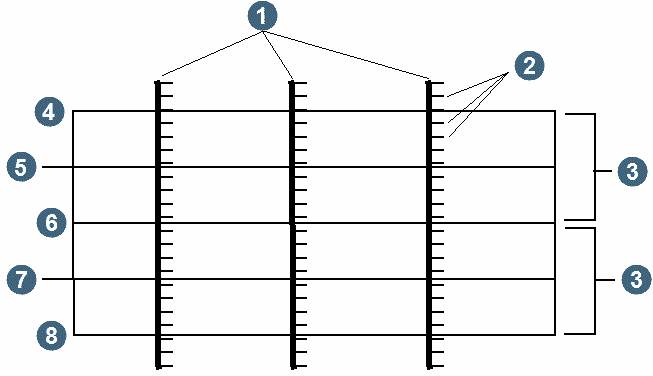
1. drill holes 2. samples 3. composite formed 4. 310 5. 300 6. 290 7. 280 8. 270 |
In this example an elevation range of 280, 300, 20 was specified with an extent of 10 and a type of `+-'.
Note: If you choose the +- method you should use an extent which is equal to half the spacing between the required composite elevations since the extent is applied both below and above the nominal elevation.
Define the output class range
Enter a range which defines the classes into which the resultant data is to be sorted. The value entered here will determine the string number to which any given composite will be assigned. This is useful for further processing when plotting or viewing in the Graphics module as it makes it very easy to assign different colours to different strings for a greater impact. Note that the classification is applied to the values for the first field name which is defined on the DEFINE SAMPLE FIELDS TO COMPOSITE form. Points which fall within the first class range will be assigned to string 1, points in the second class range will be assigned to string 2 etc.
There are two possible circumstances where the results may not be as you might expect. These are:
-
No class defined for the value of the first element.
If the output class range defined is such that some composite values do not exist in any classification group then the composite value will be discarded from the resultant file. If this situation occurs a message will be displayed to advise you of the number of points that have been discarded.
The text of the message will be like:
xxx points in elevation composite Z=zzz are not classified and are excluded from the result. Ensure the classification grade range is suitable. -
Not possible to classify the value for the first element.
If there is inadequate length support to create a composite for a drillhole in a particular elevation band then a blank value will be output in the appropriate description field rather than a numeric value. See the Minimum acceptable % of interval below for more details.
The text of the message will be like:
xxx points in elevation composite Z=zzz have no value for the first element (possibly because of inadequate length support) and have been assigned to string 32000
Minimum acceptable % of interval
If the total vertical length of the samples for a drill hole when expressed as a percentage of the vertical height of the elevation bounds of the composite, is equal to or greater than this threshold percentage then a composite value for the drill hole will be saved.
When extracting composites for multiple elements, a drillhole will be completely discarded only if there is inadequate length support for ALL elements. If just one element has sufficient length support then a point is saved. Any element that has insufficient length support will be represented by a blank value in the description field.
Threshold dip for channels
Holes which are within this angular tolerance of the horizontal are treated as channel samples, and one composite is extracted per discrete sample from the hole. Note: These composites may not be representative of the same length sample as composites from other, more vertical holes.
Composites representing different length sample intervals should not be used for statistical or geostatistical purposes. Downhole compositing is recommended to obtain equal length samples from horizontal holes.
Dilute negative samples
In certain conditions, sample values for some elements may be missing. If this occurs special sentinel values are usually stored to indicate the absence of meaningful sample data. Generally negative values are stored to indicate the absence of data. There are two ways in which this absence of data may be treated:
By responding with "Y"es, the sample will take on an assumed value of 0 (zero). This has the effect of reducing or diluting the final averages.
By responding with "N"o, the sample will be ignored completely and it will have no effect on the final result.
Table
Enter the name of the Interval table from which the sample data is to be extracted.
Optional weighting fields - Field Name, Default
If required, the calculation of the grades/qualities in the composite samples may be weighted by some other field/s in the sample table in addition to the length weighting which is already performed.
Typically, additional weighting fields used would be specific gravity and/or recovery. A maximum of 5 additional weighting fields may be used. Enter the field name/s which are to be used to provide the additional weighting criteria for the creation of the composite intervals.
Under some circumstances it is likely that no values may be available for the weighting field for some samples. The Default input field permits a reasonable default value to be defined to cover this circumstance.
The default value is used in preference to the stored value in the table when either a null value is present or when the value present is less than zero.
Choose Apply from the COMPOSITE BY ELEVATION form to display the DEFINE SAMPLE FIELDS form.
Table
Display only. The name of the table from which the samples are to be extracted is displayed here.
Field name
Enter up to 10 field names from the table shown above which are to have elevation composites calculated.
Choose Apply from the DEFINE SAMPLE FIELDS TO COMPOSITE form to display the DEFINE QUERY CONSTRAINTS form for the collar table.
Define constraints for the query on the collar table to selectively extract drill holes for processing.
Choose Apply from the DEFINE QUERY CONSTRAINTS form for the collar table, to display the DEFINE QUERY CONSTRAINTS form for the requested sample table.
You may wish to selectively extract samples for processing based on some values which may be stored in the Interval table which is being processed. This form lets you define a set of query constraints which are applied to the interval table to permit you to control the samples which are extracted for processing.
Choose Apply from the DEFINE QUERY CONSTRAINTS form for the requested sample table to commence processing.
Processing
All drill holes which match the selection criteria defined on the DEFINE QUERY CONSTRAINTS form for the collar table are processed. After all drill holes have been processed, one string file will be created for each elevation composite. If no composites are produced for one of the elevation composites then a file will not be created for that level.
Result
The output from Composite By Elevation will be one string file for each of the specified composite elevations. These files contain the following information:
-
the Y, X, Z coordinates of each point. This is the point where each hole intersects the elevation level, that is if the drill hole intersects the composite elevation. For drill holes which don't intersect the composite elevation the Y and X values are the mean of the sample mid-points which have been used to calculate the composite and the Z value is the same as the composite elevation. For channels however it is the Y and X location of the sample mid-point and the Z value is the same as the composite elevation.
-
The length weighted average of each of the elements of interest are stored in the D1, D2, D3, etc. fields of the points in the string file. In some cases a description field may be blank. This will only occur if no positive value for the element in question was found to intersect with the composite elevations.
If optional weighting fields have been used then the composite grades/qualities will be weighted by length as well as the optional weighting fields.
-
The Hole ID of the drill hole is stored in the second last description field of the string file. If, for example 2 elements were requested, then the Hole ID will be found in D3.
-
If optional weighting fields are used then the total weight of the samples comprising the composite sample will be found in the last description field.
Messages
Upon completion of processing the name of the output string file which is created and the number of holes which have been processed will be displayed in the message window.
Note: Drill hole data - If no samples in a drill hole intersect the nominal elevation for the middle of the composite then a point representing the drill hole will not appear in the resultant string file.
Further Processing
The resultant string files can be used to produce plots of the composited data, either on the screen using GRAPHICS, or hard copy plots using PLOTTING. They could also be used as input to the GEOSTATISTICS module, since they represent bench composite data of equal length.