


Stope Slicer
You use this function to split a solid into multiple smaller solids. You can use this function to split an ore body into stopes, pillars, and crown pillars.
STOPE SLICER allows you to split a resource solid into stopes, splitting the solid by physical size (using planes, elevation, or by length along a centreline) or by target value (volume or mass of the stope). STOPE SLICER also evaluates the new solids to allow you to report on volume and tonnage, as well as block model grades.
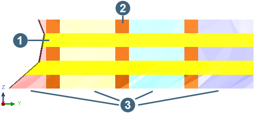
The following image shows a section view of a sliced stope.
|
1. crown pillar 2. pillar 3. four stopes |
Prerequisites: A valid solid to slice is displayed in Graphics. If you want to slice the object using planes, the planes must already exist.
To run this function: Choose Design > Stope Design tools > Stope Slicer, or...
The Stope Slicer form contains the following tabs.
 Note: The Stope Slicer form does not display all fields all the time. When you choose a different Slice option, or select a different Stope method, the fields on the Stope Slicer form change.
 Slicing
On the Slicing tab, you specify how to slice the object into stopes or levels. You create pillars by leaving gaps between the stopes. You create crown pillars by leaving space between the levels.
Fields on the Stope slicer form, Slicing tab
| Field | Description |
|---|---|
| Active layer | The name of the solid you are slicing. If Active layer is blank, open the DTM file you want to slice, click Select and select the DTM in Graphics. |
| Select | You use the Select button to select an open DTM to slice. |
| Object |
The triobject, of the solid, you are slicing. Only that triobject is sliced, so to slice an entire solid, make sure the entire solid has the same triobject number.
|
| Trisolation | The trisolation number of the solid you are slicing. Only this trisolation is sliced. |
| Slice |
This setting determines whether to slice the solid horizontally (Levels only), vertically (Stopes only), or both horizontally and vertically (Levels and Stopes). |
| Stope method |
This setting determines how the object is sliced vertically. Stope method is available only when Slice is set to Levels and Stopes, or Stopes only.
|
| Levels | |
| Slice using |
|
| Plane group | The plane group of the planes you want to use to slice your levels. These can be horizontal or inclined planes. |
| Select centreline | Allows you to select a centreline string, in Graphics, that you can use to slice the object if you have chosen a centreline Stope method. |
| From and To |
When you are slicing by levels and stopes, using a centreline, and slicing levels by elevation, you can use different centrelines on different levels. From and To allow you to specify the elevations on which to use each centreline string. From and To define the slicing levels. Depending on your Slice Using value, you define the slicing levels either as Z elevation values, or as planes. When creating stopes using a centreline, you can enter a different centreline for each level that you enter in this table. |
| Layer | The name of the layer that holds the centreline string. This field, and the String and Segment fields, are filled in when you select the centreline string. |
| String | The string number of the string. |
| Segment | The segment number of the string. |
| Stopes | |
| Plane group | The plane group that contains the planes you are using to slice the object. It is valid to use vertical or inclined planes to slice stopes. |
| From plane |
The plane that is the near edge of the first slice. If there are multiple rows, the second From plane field is the plane that is the near edge of the second slice, and so on. |
| To plane |
The plane that is the far edge of the first slice. If there are multiple rows, the second From plane field is the plane that is the far edge of the second slice, and so on. To add an additional row, press TAB in the To plane field.
|
| Stope length | The width of each stope. When you use a target method, the length of the stope you create is a multiple of this value. |
| Pillar length | The width of each pillar. Pillars are created at this length after the stope is created. |
| Target |
|
| Target value |
The minimum tonnage or volume, depending on the Target option, that must exist in each stope. Using tonnage as an example, after the STOPE SLICER function has sliced the ore body, if the tonnage of any of the new stopes is less than the Target value, the stope length of the stope is increased by the Stope length so that the length of that specific stope is doubled.
|
Examples
These examples show you how you can fill in the Slicing tab to achieve a specific slicing result.
This example uses planes, which you would create before using STOPE SLICER.
| Slice: Stopes only | |
| Stope method: Planes | |
| From plane: 7110n | To plane: 7150n |
| From plane: 7160n | To plane: 7200n |
| From plane: 7210n | To plane: 7250n |
| Slice: Levels only | |
| Slice using: Elevation | |
| From: 920 | To: 960 |
| From: 970 | To: 1010 |
Fields on the Stope slicer form, Exclusions tab
You might have a drive, or other existing workings, that you want to remove from the stope or from the pillars or crown pillars. When you add one or more objects as exclusions, you create stopes, pillars, and crown pillars that have the excluded objects removed from them.
Note: When you are slicing to a target, STOPE SLICER removes the volume of the exclusion as the final task after it has generated each slice.
| Field | Description |
|---|---|
| Select | Allows you to select a solid, that is open in Graphics, to exclude from the stopes. |
| Layer | The name of the layer that contains the excluded object. This field is filled in after you have selected the object you want to exclude. |
| Object | The object number of the excluded object. |
| Trisolation |
The trisolation number of the excluded object.
|
When you slice an object, the stopes, pillars, and crown pillars you create are given a Name property. The settings on the Naming tab determine the value of that property.
Fields on the Stope slicer form, Naming tab
| Field | Description |
|---|---|
| Stope prefix |
The prefix to apply to the name of each stope.
|
| Start at |
The automatically incrementing part of the name. The increment can be numeric or alphabetic. For example, a Start At value of 01A will cause the next values to be 01B and 01C, until 01Z, when they become 02A. Similarly, a Start At value of 001, will cause values of 002, 003 … 010. The way you specify the Start At value determines a format for the rest of the values, and any character other than numeric or alphabetic is placed in the correct place. For example, “01-A” causes values of 01-Z, 02-A, with the hyphen always located in the same position in the name. |
| Increment method | Determines whether or not stope numbering is reset at the start of each horizontal level. If you select reset at each level, the Start At value is reset to the defined Start At value at each level. |
| Pillar name | The suffix for pillars. |
| Crown pillar name | The suffix for crown pillars. |
| Start object ID | The triobject number of the first stope. Objects are numbered from this value upwards. They are in horizontal order of numbering first, and then in vertical order of numbering. |
| Label separator | The character to use to separate the Prefixed label in the stope name from the rest of the stope name. |
| Area label |
The name of a new property you want to create and apply to the stopes. The value of this property is added as a prefix to the name of the stope - that is, to its Name property. These values are also written to the object that is created (and the values are stored in the file) as a named attribute.
|
| Value | The value of the new property you defined in Prefixed label. Press TAB to create an additional property. |
| Sample names | This section shows you a preview of the names you will create. You can experiment by changing the fields in the Stope Naming section, and then viewing the result here. |
Fields on the Stope slicer form, Block Model tab
| Field | Description |
|---|---|
| Evaluate using block model | Allows you to use the attributes in an open block model to provide grade and density for the Stope Slicer report. |
| Block model | Select the block model you want to use when evaluating stope solids. |
| Specific gravity by |
|
| Attribute | The attribute, in the block model, that stores density. |
| Replace negatives with | Any negative value in the density attribute in the block model, is replaced by the Replace negatives with value. For example, if you have some air blocks, in the model, that currently have a negative density, you might use a Replace negatives with value of 0. |
| Value | The density to use for blocks in the block model. You use either Specific gravity value or Specific gravity attribute. You cannot use both fields. |
| Use partial percentages |
|
| Precision | Precision level 1 means that Surpac splits each block into 8 when doing sub-blocking. Precision level 2 means that each of those 8 subblocks are split into 8 more subblocks, and so on. The sub-blocks that are within the sliced object provide their data to the Stope Slicer report. |
| Ore/rock type attribute for classification |
This optional field allows you to specify an attribute that indicates whether a block is ore or waste. The Stope Slicer report then shows how much ore is in each stope, and how much waste. The attribute must have a type of character, integer, or be a calculated attribute that evaluates to a character or integer. |
| Attributes | The attribute that stores the resource grade. You can add additional rows for each additional resource of interest. |
| Contained metal factor | A number that is multiplied by the grade when the Stope Slicer report is produced. Usually Contained metal factor is 1. Contained metal factor is useful if you need to convert grade from one unit of measurement to another, for example from ounces per tonne to grams per tonne. |
| Metal units | The unit of measurement that you would like to appear in the Stope Slicer report in the column that shows the weight of resource in each stope. |
| Replace negatives with |
Any negative value in the resource grade is replaced with the Replace negatives with value. This is useful when a negative grade in the block model has been used to mark a block as waste. In that situation you could use a Replace negatives with value of 0. If you did not replace negatives , the blocks with a negative grade would reduce the contained metal values shown in the Stope Slicer report. |
Fields on the Stope slicer form, Results tab
| Field | Description |
|---|---|
| New stopes layer | The name of the layer that holds the new stopes. |
| Randomise colours | Random colours are used to colour the stopes. |
| Stopes start colour | The colour of the first stope. |
| Stopes end colour | The colour of the end stope. |
| Colouring method |
|
| New pillars layer | The name of the layer that holds the new pillars. |
| Pillars colour | The colour of the pillars in Graphics. |
| New crown pillars layer | The name of the layer that holds the new crown pillars. |
| Crown pillars colour | The colour of the crown pillars in Graphics. |
| Report filename | The name of the Stope Slicer report. |
| Format | The file format of the report, for example .csv. |
Output
Three new layers are created, in the Layer Manager. The three layers hold the stopes, pillars, and crown pillars respectively. If your inputs do not cause any pillars or crown pillars to be created, the layers for these objects are not created. If you typed an Report filename, a report is created that shows the volume of each stope, pillar, and crown pillar. If you are using block model attributes to provide data, the report can also show the mass of each object, grade, and mass of contained metal.
The values written to the report (such as names, volume, block model attribute) are all also written directly into the stope solid. The values are saved in the file if you save the output layers.
Note: Some of these values, such as block model grades, are invalidated (and therefore deleted) when you modify the solid.
 Tip: To view the values in the Properties window, click the Select tool from the Tools toolbar, and select the trisolation.
Tip: To save one of the three layers, activate the layer and save it. If you want the objects in the layer to keep the same colour each time you reopen them, select the Save styles box when you save the layer.
| Message | Description |
|---|---|
Warning: A calculated stope slice may not cover the whole solid. Please check the result carefully.
|
When you are slicing along a centreline, if the centreline is not straight, two slices can intersect each other. The part of the stope that was in both slices is removed from both slices. Try using a smooth centreline string that changes direction more gradually, rather than a string with sudden changes of direction. The SMOOTH STRING function might help you create the smooth string. Alternatively, use the Start plane and length stope method rather than the Centreline and length string stope method. |