


Slicing objects
Task: View the data
- Click Reset graphics
 .
. - Open ringex1.dtm in Graphics.
- Rotate the data to get an ides of the shape of the solids models.
- Choose Display > Hide everything.
- Choose Display > Surface or Solid.
- Enter the information as shown, and click Apply.
- Choose Display > Hide everything.
- Choose Display > Surface or Solid.
- Enter the information as shown, and click Apply.
- Choose Display > Hide everything.
- Choose Display > Surface or Solid.
- Enter the information as shown, and click Apply.
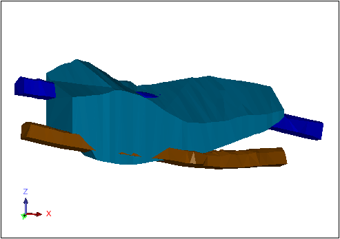
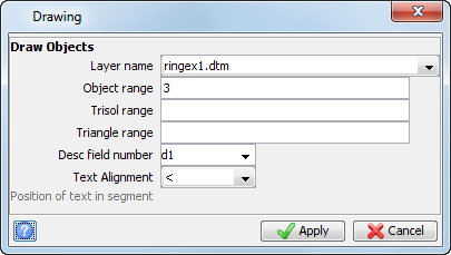
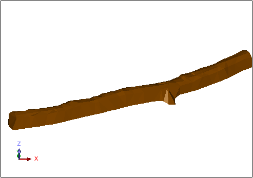
Object 3 is displayed.
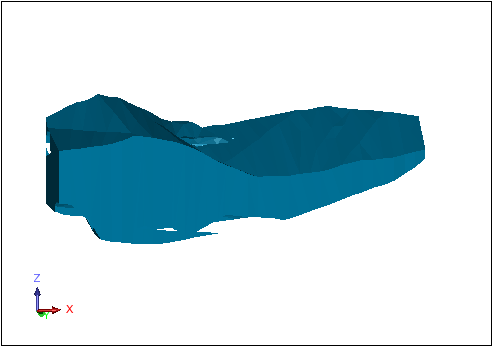
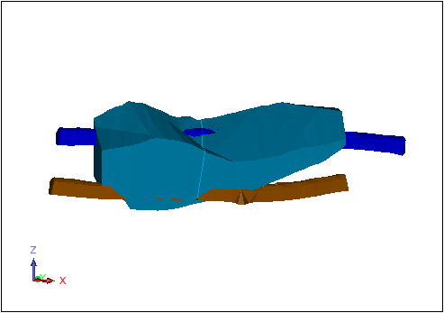
 Note: Object 3 represents the ore zone. It contains holes where the drives pass through it.
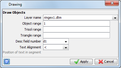
Object 1 is displayed.
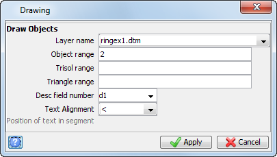
Object 2 is displayed.
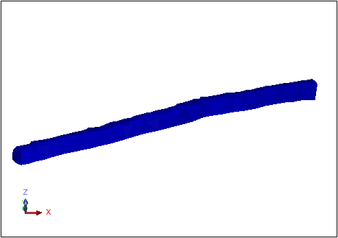
Objects 1 and 2 are the drives, created from survey data. Object 3 was created by outersecting the solid of the ore zone by the solid of the drives.
|
|
|
|
Objects 1 and 2 |
Object 3 (outersected by objects 1 and 2) |
|---|
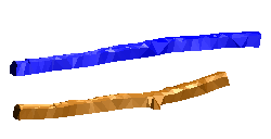

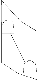
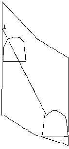
Note: It is a good idea to use outersected solids for creating ring design slices, since the toe (or end) of the hole will be located at the point where the hole intersects the stope. As shown below, if the 3D solid of the stope is not outersected by the drives, you might not achieve the desired result.
|
|
|
|
Hole drilled in stope outersected by drives |
Hole drilled in stope NOT outersected by drives |
|---|
Task: Slice the solid
- Click Reset graphics .
- Open ringex1.dtm in Graphics.
- Open cl1.str in Graphics.
- In the Layers pane, right-click ringex1.dtm, and select Make active.
- Choose View > Surface view options > Hide triangle faces.
- Click Zoom all
 .
. - Choose Solids > Solids tools > Section using centre line.
- Click a point below and to the left of the southwest end of the centreline, as shown.
- Click the other endpoint of the centreline by positioning the cursor northeast of the northeast endpoint of the line.
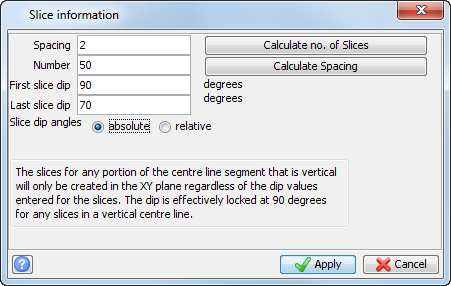
- Enter the information as shown, and click Apply.
- Enter the information as shown, and click Apply.
- Click Section view
 .
. - Choose Reset graphics , and click Apply.
- Open 1055sec25.str in Graphics.
- Open ringex1.dtm in Graphics.
- Rotate the data to verify that the section has been created correctly.
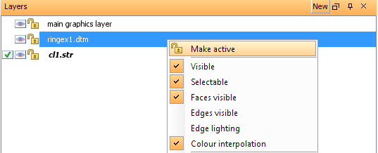
You will use the southwest endpoint of cl1.str as the point from which to create the first ring. In this example, the rig will start from the southwest end of the stope and work toward the northeast, numbering the rings 1,2,3,through 50.
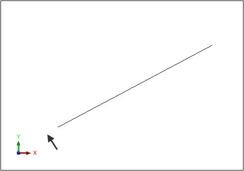
Surpac will choose the nearest location on the line.
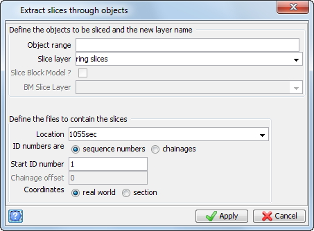
The sections are displayed.
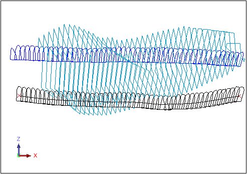
The solids section is displayed.
Note: To see all of the steps performed in this chapter, run 02_slice_objects.tcl. You need to click Apply on any forms presented.