


Getting started with stope design
To successfully use stope design you need:
- a block model or solid representing the geological ore body
- planes that intersect the block model or solid
You will create one polygon on each of these planes, and project outwards from the polygon to create the stope.
The underground_mine_design data set includes a block model and planes.
Before you start stope design, it is useful to set up your workspace with the toolbars that you will use later.
Task: Display block model and set up toolbars
- Drag training.mdl into Graphics.
- Constrain the block model to blocks whose gold grade is 0.3 or greater.
- Display the block model.
- Right-click in Graphics, and choose 2D Planes mode.
- Expand the Planes panel, right-click on plane sd1\7130N, and choose Set active.
- Drag the Digitise toolbar to Graphics to undock it.
- Right-click in the toolbar area, and choose Toolbars > Underground Design to show the Underground Design toolbar which includes buttons for the Stope Design functions.
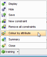
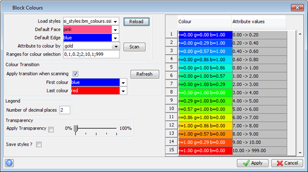
- Colour the block model by gold attribute using a Range for colour selection of 0,1,0.2;2,10,1;999.
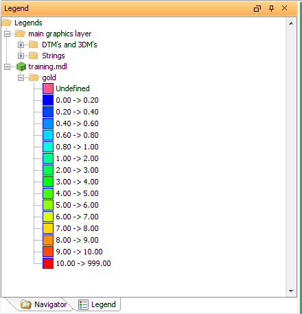
- In the Navigator, click the Legend tab, and expand the gold folder.
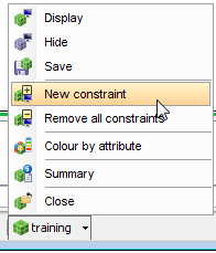
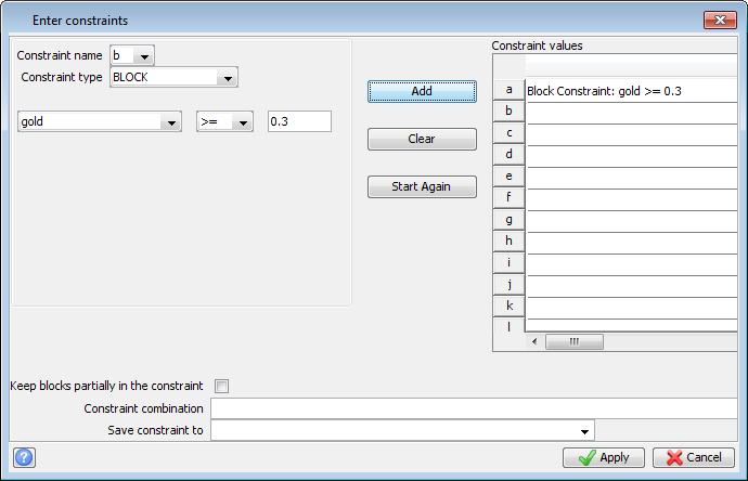
 Tip: If you cannot see the blocks, select View > Zoom > All.
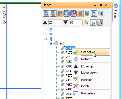
Tip: If the block edges are not visible, click Draw block model as blocks or polylines in the Planes panel.

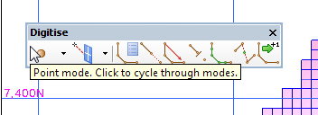
With the Digitise toolbar close to the block model, it is easier to create the polygons.

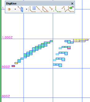
You can consider the deposit to be two distinct ore bodies, a larger ore body to the west, and a thinner ore body to the east. In this document, the procedures are written on the assumption that the western ore body will be mined.