Task: Create and evaluate subsequent polygons
After you have created and evaluated the first polygon, you can activate each of the other planes, and create a polygon on each plane.
- Select Customise > Default preferences.
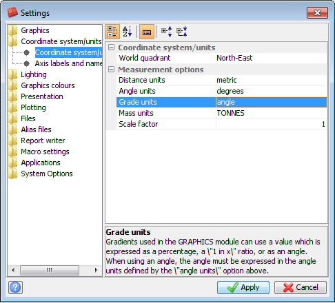
- Under Coordinate system/units, set Grade units to angle, and click Apply.
- Press F12 to activate the next plane.
- In the function chooser, type CUTTING PLANE REMOVE, and press ENTER.
- Start a new segment, digitise a polygon around the ore body, and press ESC.
- On the Underground Design toolbar, click the Query block model
 button, and click Apply.
 - Right-click in Graphics, and choose 3D Planes mode.
- Show the design_evaluation_solids layer.
- Click Set Large Projections in the Planes panel.
- Right-click in Graphics, and choose 2D Planes mode.
- Hide the design_evaluation_solids layer.
- In the Planes panel, click Revert to plane corridor.
- For each remaining plane up to 7530n, activate the plane, digitise a polygon, and evaluate the ore body.
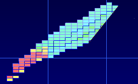
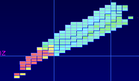
The cutting plane you previously defined is now cutting into the ore blocks in this plane. You can remove the cutting plane by running CUTTING PLANE REMOVE.
 Note: You cannot run DELETE CUTTING PLANES unless you exit stope design. Run CUTTING PLANE REMOVE instead.
 Tip: If a solid is obscuring your view, click Draw triangulations as triangles or polylines
 to hide it.

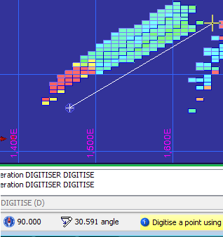
The Status bar displays the gradient from the last point you digitised to the pointer position. The gradient is displayed as an angle because you selected angle for the grade units in the Settings form. Viewing the grade units as angles is an alternative to using Drafting mode to ensure you honour a particular slope angle.
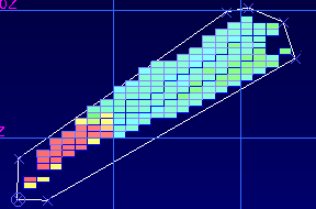
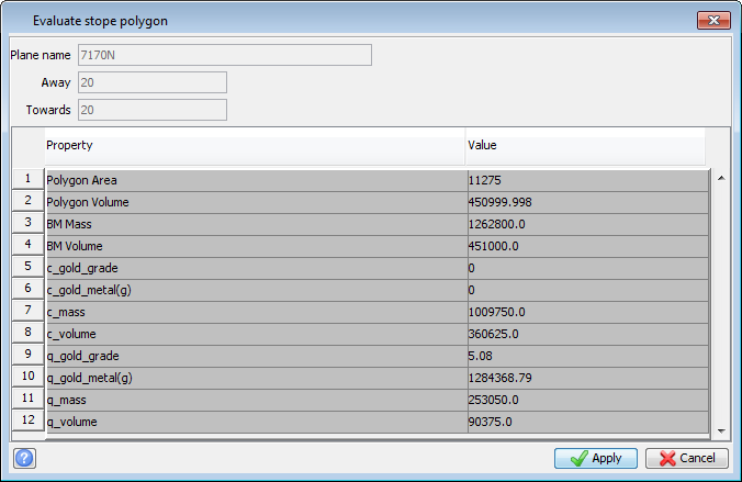
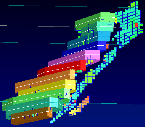
Graphics shows the new working stope design in context. You can rotate the view to see how the stope design is progressing.
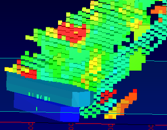
You might decide to increase or decrease the size of this part of the stope. To do so, you can edit the stope polygon and then evaluate it again.