


Task: Slice by elevation
To get familiar with the basics of Stope Slicer, you will perform a simple task, slicing a solid by elevation.
- Click Reset Graphics.
- Close any block model that is open.
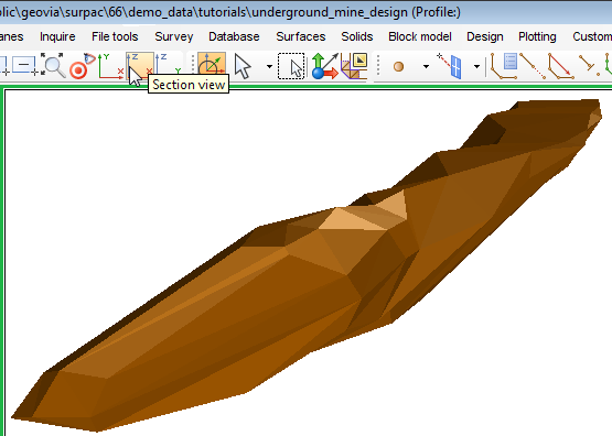
- Drag finalstope.dtm into Graphics.
- Click Section view
 on the Navigate toolbar.
 - If the Underground Design toolbar is not already displayed, right-click in the toolbar area, and choose Toolbars > Underground Design to show the Underground Design toolbar.
- Click
 on the Underground Design toolbar to start the Stope Slicer.
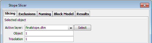
 - On the Slicing tab, click Select, and click on the ore body in Graphics.
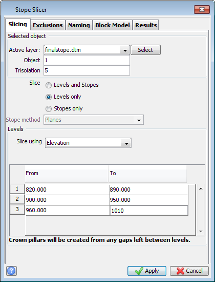
- In the Slice section, select Levels only.
- In the Slice using section, select Elevation.
- In the 'From To' table, enter From: 820, To: 890, From: 900, To: 950, and From: 960, To: 1010.
- Click Apply.
- Click the crown pillars layers to make it invisible.
- In the function chooser, type SAVE ALL LAYERS AS.
- Click Apply.
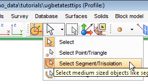
- On the Tools toolbar, click the Select tool, and choose Select Segment\Trisolation.
- Select one of the stopes in Graphics.
 Note: If you have not created finalstope.dtm, use the finalstopeZ.dtm that is supplied with the data set.
You can also slice levels using planes, if you have created the planes already.

The ore body is sliced into three stopes with two crown pillars in between. By default, crown pillars are displayed in yellow.
In the Layer Manager, you can see two new layers, one for the stopes, and one for the crown pillars. In this example there are no (vertical) pillars, but there are (horizontal) crown pillars.

The stopes layer and the crown pillars are not yet saved. You do not create files for the stopes and for the crown pillars until you save the layers in which they are temporarily stored.
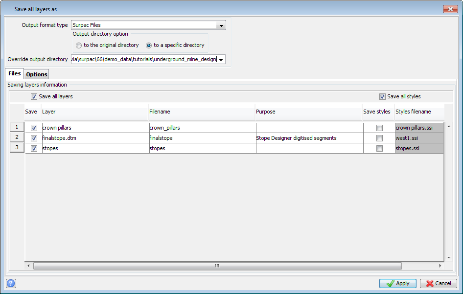
Note: To make sure that the stopes are always displayed with the same colour (red in this example) you must select the Save all styles check box.
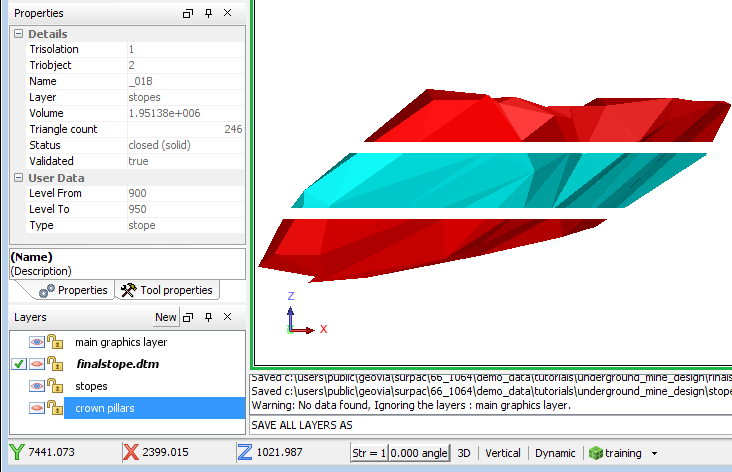
The Properties pane displays some details of the stope.