


Task: Define exclusions in stope slicing
You can exclude a valid solid from a stope when you slice so that the volume of the excluded solid is not included in the stopes (or pillars or crown pillars) that you create. This is useful when you have drives, or existing workings, that are already modelled as solids.
- Click Reset Graphics.
- Open ugdesAlt.dtm.
- Open stopesAlt.dtm.
- Click the Section view icon
 on the Navigate toolbar to view the data in section view.
 - Rotate the image so you can see the three drives.
- Type STOPE SLICER in the Function Chooser, and press ENTER.
- Select the Exclusions tab.
- Click Select, and, in Graphics, select one of the three blue-green drives.
- Select the other two blue-green drives in the same way, and press ESC.
- Select the Slicing tab.
- Click Select, and select the stope on the left.
- Select Levels and Stopes.
- For the Stope method, select
Planes. - For Slice using, select Planes.
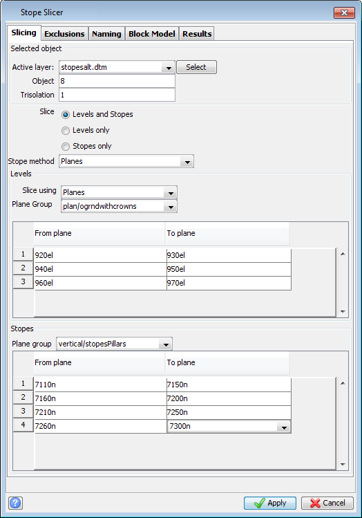
- Fill in the 'From plane To plane' tables, and the Stopes section, as shown.
- Click the Results tab.
- In the New stopes layer field, type
stopesNew. - In the Output Report File Name field, type
ex1. - Click Apply.
- Right-click on ex1.csv in the Navigator, and choose Open.


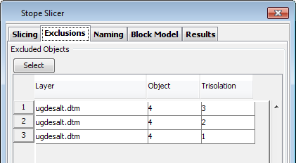
You have specified to exclude the three drives.
 Note: If
 Planes is not listed in the Stope method list, you do not have any horizontal planes available. You can copy the planes supplied with this data set to your planes folder, and then right-click in the Planes panel, and click Refresh. The default planes folder is C:\Users\Public\GEOVIA\Surpac\<version>\share\planes.

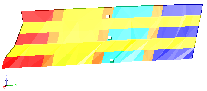
The solids that are created have holes where the drives were.

The report shows you the volume of each stope, pillar, and crown pillar.