


Creating a centreline design
Task: View the data
- Open stopes1.dtm in Graphics.
- This file represents two parallel ore zones.
- Open ugdes_final1.dtm in Graphics.
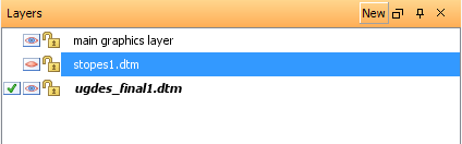
- Click the eye icon in the Layer Manager for stopes.dtm to hide the stopes layer.
- Choose View > Surface view options > Hide triangle faces to hide the drives.
- Choose Display > Strings > With string numbers.
- Enter the information as shown, and click Apply.
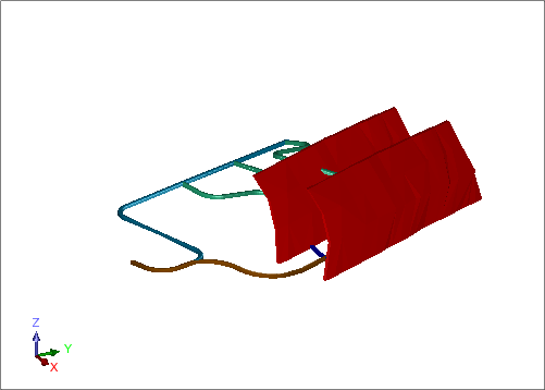
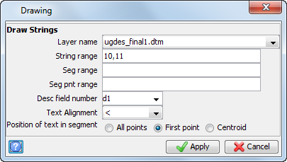
Strings 10 and 11 represent the centreline string numbers in the final design.
The centreline string is displayed.

Task: Create a centreline between ore zones
- Click Reset graphics
 .
. - Open lev215.str in Graphics.
- Open stopes1.str in Graphics.
- Spin the data around to get an idea of how the strings are formed in 3D space.
- Choose Display > Strings > With string numbers, leave the fields blank and click Apply to display all strings with numbers.
- Choose Inquire > Point properties, and click several different segments.
- Choose Display > Hide everything.
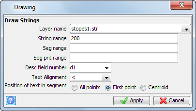
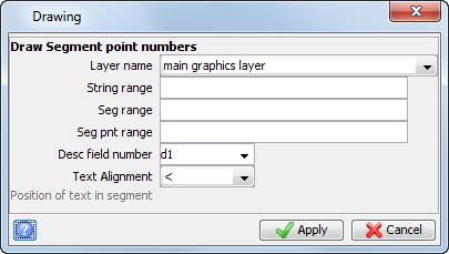
- Choose Display > Strings > With string numbers.
- Enter the information as shown, and click Apply.
- In the Layer Manager, right-click main graphics layer and choose Make active.
- Click the Design string number button
 on the Status bar.
 - Enter the information as shown, and then click Apply.
- Choose Create > Digitise > New midpoint.
- Click two points on the north end of the ore zones to create a point midway between the two selected points, as displayed.
- Click two points on the south end of the ore zones to create another point midway between the two selected points, as displayed.
- Press ESC.
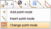
- Click the point mode drop down, and select Change point mode.
- Choose Create > Points > On line between any points.
- Click the first point created in string 10 (that is, the point to be moved), and then click the second point created in string 10.
- Enter the information as shown, and then click Apply.
- Press ESC.
- Choose Create > Points > Insert point mode.
- Choose Create > Points > Multiple points by subdividing.
- Click the northern end of string 10, then the southern end of string 10.
- Enter the following information, and click Apply.
- Press ESC.
- Choose Display > Point > Numbers.
- Enter the information as shown, and click Apply.
- Save the centreline string to the file ugdes1.str.
 Note: The string numbers correspond with the Z value of the strings.
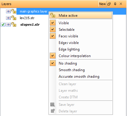
The main graphics layer currently does not contain any data.
As shown in the final design previously, the string used to create the main drive between the two ore zones is string 10.
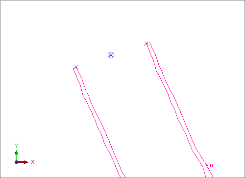
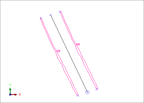
The Z value of the created points will be equal to the average of the Z values of the two selected points. In this case, where the Z value of both points is 200, the Z value of the new points will also be 200.
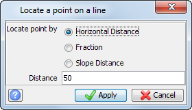
The point will be moved 50 metres as displayed.

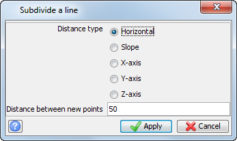
The centre string is displayed.
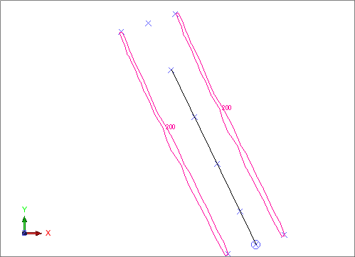
The points inserted along the centreline are displayed.
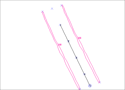
These points will be the starting points for the access drives to the ore zones.
Note: To see
all of the steps performed in this section, run _01_create_centreline_between_ore_zones.tcl.
You need to click Apply on any forms presented.
Task: Create access drives to the ore zones
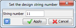
- Click the Design string button on the Status bar.
- Enter the information as shown, and click Apply.
- Choose Create > Points > Add point mode.
- Choose Create > Points > By angle.
- Click point 2, then point 1.
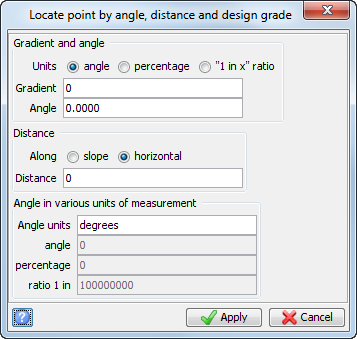
- Enter the information as shown, and click Apply.
- Without cancelling the previous function, click point 2, and then click point 1.
- Enter the information as shown, and then click Apply.
- Choose Create > New segment.
- Choose Create > Points > By angle.
- Click point 2, then point 1 again.
- Enter the information as shown, and click Apply.
- Without cancelling the previous function, again click point 2, then point 1.
- Enter the information as shown, and click Apply.
- Choose Display > Hide temporary markers.
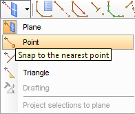
- Click the Snap mode drop-down and select Point.
- Choose Edit > String > Copy.
- Click string 11 near point 1 on string 11, drag to point 2 on string 10, then release.
- Enter the information as shown, and click Apply.
- Click near point 1 of string 11 again, drag to point 3 on string 10, and release.
- Enter the information as shown, and click Apply.
- Press ESC.
- Click Plan view
 .
. - Choose Edit > Trim > Clip by selected segment.
- Enter the information as shown, and click Apply.
- Click one segment of string 200.
- Enter the information as shown, and click Apply.
- Click the other segment of string 200.
- When the form appears again, click Cancel.
- Choose Edit > Segment > Delete
- Click the portion of each segment extended beyond the ore zones.
- Press ESC.
- Choose Display > Hide temporary markers.
- Save as ugdes1.str, overwriting the previous contents.
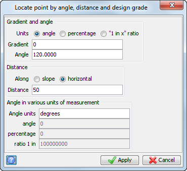
This creates a new segment of string 11 that will extend beyond the western ore zone as shown.
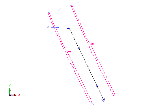
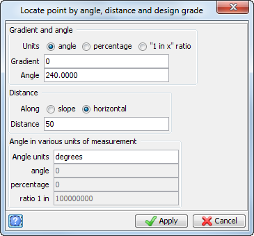
You now have two segments of string 11 representing the centreline of ore access drives left and right off the main drive.
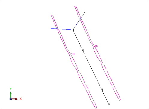
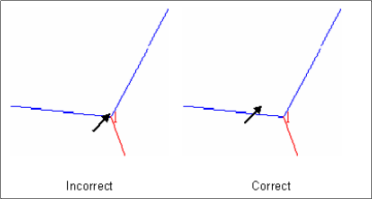
Note: In order to correctly select a string or segment in Surpac, do NOT select a point common to two or more strings. In this case, in order to select string 11, you would not want to position the cursor right on top of point 1, because this point is common to string 10 and string 11, and you could not be certain exactly which string you select.
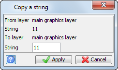
A copy of both segments of string 11 is created at point 2.
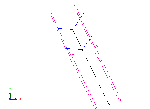
Note: There are two additional points on string 10 (point 3 and point 4) where you need access drives. You can continue using the String Copy function to create drives for these points.
The eight access drives are displayed.
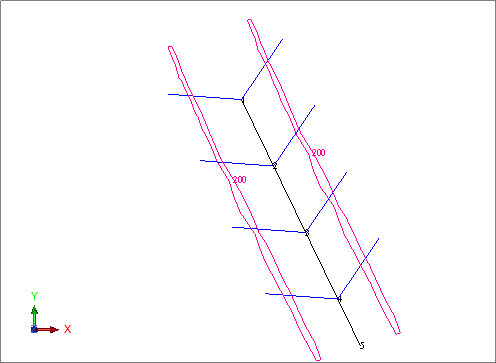
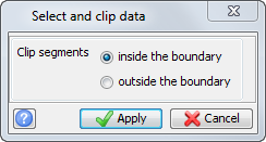
You will see all portions of segments inside both ore zones removed.
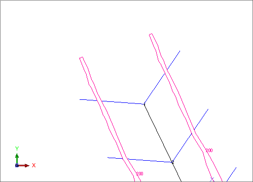
The drives are displayed.

Note: To see
all of the steps performed in this section, run _02_create_access_drives_to_ore_zones.tcl.
You need to click Apply on any forms presented.
Task: Create the main decline
- In the Layers pane, right-click lev215.str and choose Make active.
- Choose Display > Strings > With string numbers and click Apply on the form, to display all strings in the layer.
- Choose Inquire > Point properties to determine the elevation of the two points.
- Choose Inquire > Bearing and Distance between two points.
- Click the end of string 1, then the beginning of string 1.
- Press ESC.
- Zoom out to see the access drives then zoom in to get a good view of points 4 and 5.
- Choose Inquire > Bearing and Distance between two points.
- Click point 5, then point 4 on string 10 in ugdes1.str.
- Press ESC.
- In the Layers pane, right-click main graphics layer, and choose Make active.
- Choose Create > Points > Add points mode.
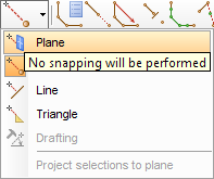
- Click the Snap mode drop-down and choose Plane.
- Use the Design string and Design gradient buttons on the Status bar to set the string to 10, and the grade to zero percent.
- Choose Display >Point > Numbers.
- Enter the information as shown, and click Apply.
- Choose Display > Point > Markers.
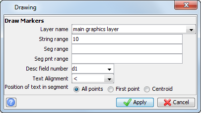
- Enter the information as shown, and click Apply.
- Choose Create > Curve at segment end.
- Click point 4, then point 5.
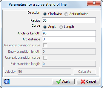
- Enter the data as shown, and click Apply.
- Press ESC.
- Zoom in so that you can see the points clearly.
- Choose Edit > Segment > Join.
- Zoom in so that you can see the points clearly.
- Click point 5, then point 7.
- Press ESC.
- Choose Create > Points > By bearing.
- Click the end of the newly created curve.
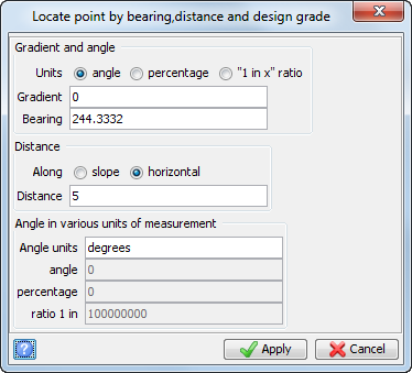
- Enter the information as shown, and click Apply.
- Choose Create > Curve at segment end.
- Click point 21, then point 22.
- Enter the information as shown, and click Apply.
- Press ESC.
- Choose Display > Hide temporary markers.
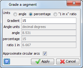
- Choose Edit > Segment > Change gradient.
- Click point 5, then point 36.
- Enter the following information, and click Apply.
- Choose Inquire > Point properties.
- Click point 36.
- Choose Edit > Segment > Break.
- Click the segment between points 5 and 6.
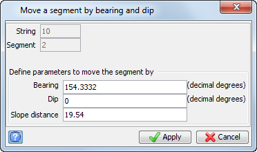
- Choose Edit > Move segment constrained by > Bearing and distance.
- Click the segment with the two curves.
- Enter the information as shown, and click Apply.
- Choose Edit > Segment > Join.
- Click the main drive first (at point 5), then click the curves (at point 7).
- Choose Edit > Segment > Change gradient.
- Click point 5, then click point 36.
- Enter the information as shown, and click Apply.
- Choose Inquire > Point properties.
- Click point 36 (that is, the southern end of curve 2).
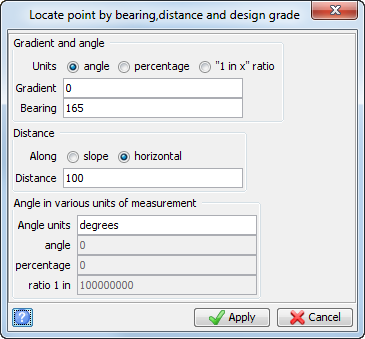
- Choose Create > Points > By bearing.
- Click point 36 (that is, the southern end of curve 2).
- Enter the information as shown, and click Apply.
- Press ESC.
- Choose Create > Points > Change point mode.
- Choose Create > Points > At intersection of two lines.
- Click point 37, then click point 36.
- Click both of the endpoints of the centreline of lev215.str (that is, string 1).
- Press ESC.
- Click the Snap mode drop-down and choose Point.
- Choose Create > Points > Insert after an existing point.
- Click point 37, and drag it to the Access Point
- Enter the information as shown, and click Apply.
- Press ESC.
- Press ESC.
- Choose Create > Points > Insert point mode.
- Choose Create > Curve from tangents.
- Click point 36, then click point 37.
- Click point 37 again, then click point 38.
- Enter the information as shown, and click Apply.
- Choose Edit > String > Clean.
- Enter the information as shown, and click Apply.
- Click string 10, the centreline string.
- Choose Display > Hide point > Markers.
- Enter the information as shown, and click Apply.
- Choose Display > Hide point > Attributes.
- Enter the information as shown, and click Apply.
- Choose Display > Hide temporary markers.
- Save the file as ugdes1.str.
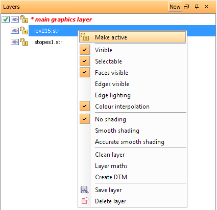


Because the bearing of the main drive between the ore zones was 334.3332, you will construct the 5 metre straight section at a bearing 90 degrees less than that. That is, at 244.3332.
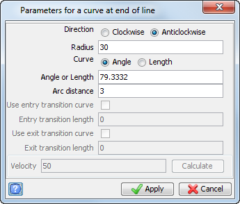
Note: The direction of the curve is anticlockwise.
The curve is displayed.
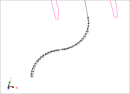
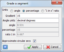
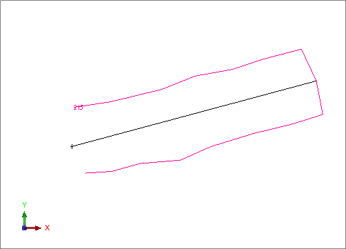
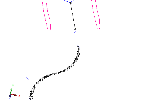
The segment is displayed.
A new point will now be created much further south as displayed.
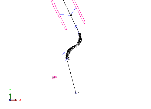
Note: It is important to select 37 first, because the first point selected will be moved.
Note: You might need to zoom in on lev215.str so that you select the correct points. It does not matter which end you select first for this string, point 37 will still be moved to the correct position as shown.
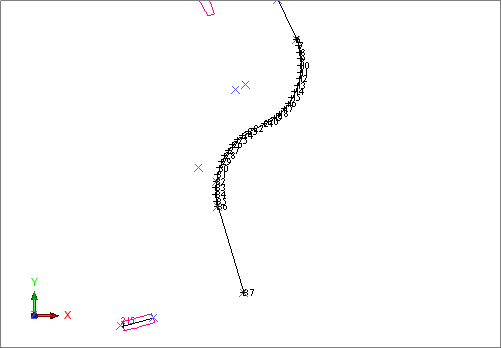
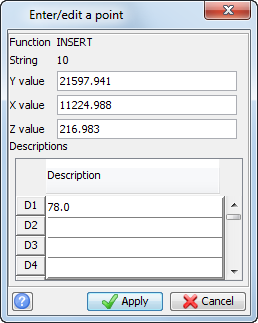
The centreline string is displayed.
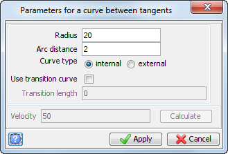
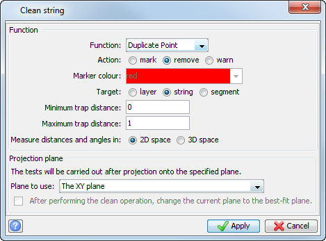
One point is removed from the string.
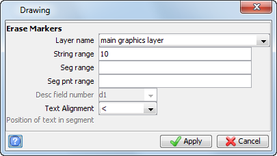
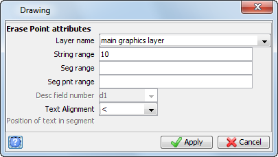
The centre string is displayed.
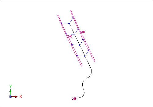
Note: To see
all of the steps performed in this section, run _03_create_main_decline.tcl.
You need to click Apply on any forms presented.