


Triangulating using centre line and profile
Task: Create a solid using centre line and profile.
- Click Reset graphics
 .
. - Open pfl1.str in Graphics.
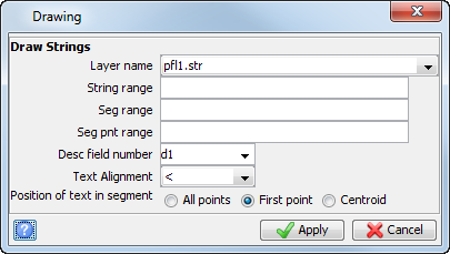
- Choose Display > Strings > With string numbers.
- Enter the information as shown, and click Apply.
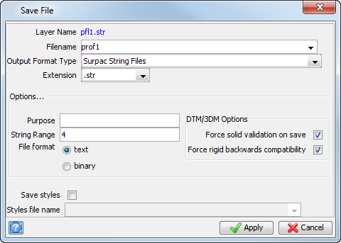
- Choose File > Save > string/DTM.
- Enter the information as shown, and click Apply to save string 4 only into prof1.str.
- Click Reset graphics .
- Open prof1.str.
- Choose View > Zoom > Out.
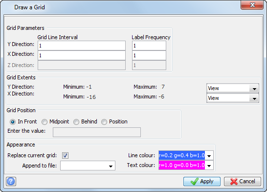
- Choose Display > 2D grid.
- Enter the information as shown, and click Apply.
- Choose File tools > String Maths.
- Enter the information as shown, and click Apply.
- Click Reset graphics .
- Open prof1.str.
- Choose View > Zoom > Out.
- Choose Display > 2D grid.
- Enter the information as shown, and click Apply.
- Click Reset graphics .
- Open dcl100.str, which represents the centre line of a decline.
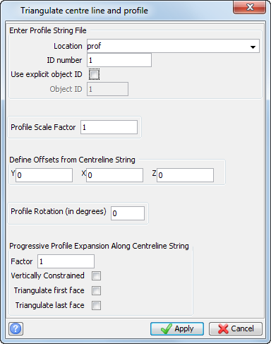
- Choose Solids > Triangulate > Using centre line & profile.
- Enter the information as shown, and click Apply.
- Click the centre line.
- Choose Display > Hide everything.
- Choose Display > Strings As lines to see how the solid has been created.
- Zoom in and use the orbit tool to make the solid easier to visualise.
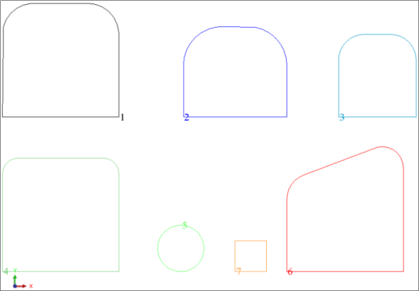
These are a series of profile strings representing the outlines of various underground features.
The profiles examples are displayed.
 Note: In order for the profile to be correctly applied to a centre line, the centre, bottom point of the profile needs to have coordinates of X = 0, Y = 0.
The profile example is displayed.
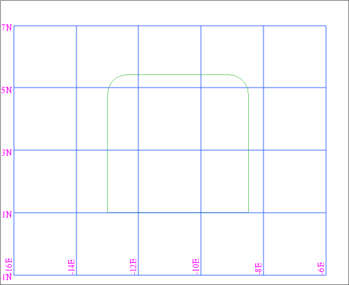
Note: The profile needs to move 10.75 in the x direction and -1 in the y direction to have its bottom centre at (0,0)
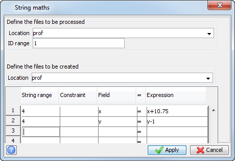
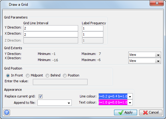
The profile is displayed.
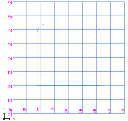
Notice that the centre, bottom point of the profile is now at (0,0)
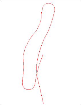
Note: The profile string is applied perpendicularly at each point in the centre line and then these profiles are stitched together to form the object.
The profiles on the centre line are displayed.
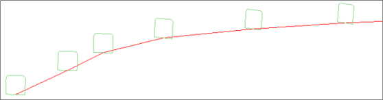
The solid is constructed by applying the profile to each point on the centre line
Note: The centre line and profile function does not save the new file automatically. If you want the file saved, you must specify a new file name.
Note: To see all of the steps performed in this task, run
_05_centre_line_and_profile.tcl. You need to click Apply on any forms presented.