


Triangulating using bifurcation techniques
Task: Perform bifurcation - one segment to many segments
- Click Reset graphics
 .
. - Open bifurc1.str in Graphics.
- Put it in a suitable view so that you can see all three shapes.
- Choose Display > Point > Markers to display all points as markers.
- Choose Solids > Triangulate > One segment to many segments.
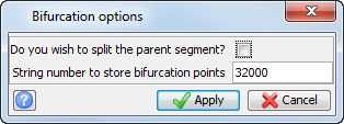
- Enter the information as shown, and click Apply
- Enter the information as shown, and click Apply.
- Click the parent segment.
- Click the opposite side of the parent segment.
- Click the left side of the parent segment.
- Enter the information as shown, and click Apply.
- Click the left child.
- Click Apply on this form and click the right child.
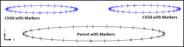
The Parent and Child segments with Markers are displayed:
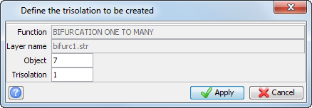
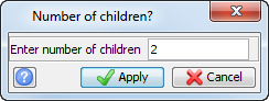
You are prompted to select the first break point on the parent segment for the first child.
Here you are being asked to select where you are going to perform the bifurcation,
You are prompted to select the second break point on the parent segment for the first child.
The bifurcation example is displayed.
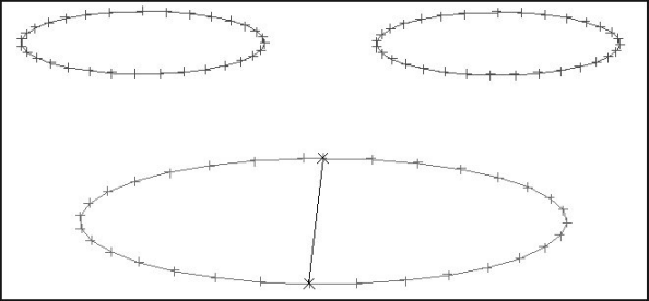
You are asked to select the portion of the parent segment to join to the first child. This means which side of the parent will you join up with which child.
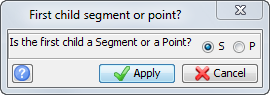
You are asked whether the next child is a segment or a point
The bifurcation example is displayed.
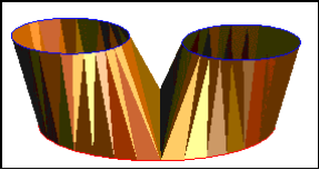
 Note: This is just one way of performing a bifurcation. The benefits are the relative simplicity and the ability to split the parent string to more than two components.
Task: Perform one segment to two segments (bifurcation union)
- Click Reset graphics .
- Open bifurc1.str in Graphics.
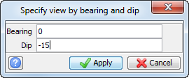
- Choose View > Data view options > View by bearing & dip.
- Enter the information as shown, and click Apply.
- Choose Solids > Triangulate > One segment to two segments.
- Enter the information as shown, and click Apply.
- Enter the information as shown, and click Apply.
- Click the parent segment.
- Click Apply, and then click the left child.
- Click Apply, and then click the right child.
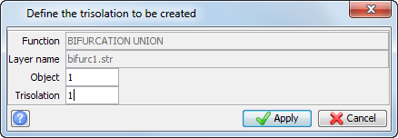
You are prompted to select the parent segment.
You are then prompted to choose whether the first child is a (S)egment or a (P)oint.
You are then prompted to choose whether the second child is a (S)egment or (P)oint.
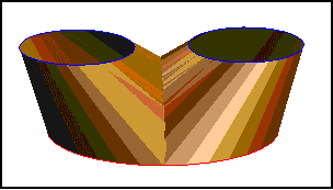
The bifurcation example is displayed.
Task: Perform bifurcation union – split parent
- Click Reset graphics .
- Open bifurc1.str in Graphics.
- Put it in a suitable view so that you can see all three shapes.
- Choose Display > Point > Markers to display all points as markers.
- Choose Solids > Triangulate > One segment to two segments.
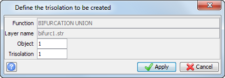
- Enter the information as shown, and click Apply.
- Enter the information as shown, and click Apply.
- Click the first break point on the parent segment for the first child (for example, point 1 as shown) .
- Click the second break point on the parent segment for the first child (for example, point 2 as shown) .
- Click the parent segment on the left side of the defined breakline.
- Click Apply, and then click child 1.
- Click the first break point on the parent segment for the second child (for example, point 3 as shown).
- Click the second break point on the parent segment for the second child (for example, point 4 as shown).
- Click the parent segment on the right side of the defined breakline.
- Click Apply and then click child 2.
The bifurcation example is displayed.
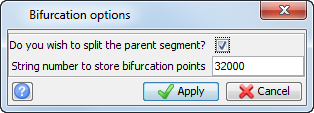
The position of the line of bifurcation is controlled by splitting the parent segment in different ways.
Note: The two breaklines defined must always overlay as shown.
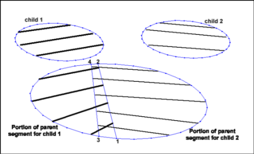
Note: The first series of prompts will define a portion of the parent segment to be assigned to the first child.
Note: The next series of prompts will define a portion of the parent segment to be assigned to the second child.
The bifurcation example is displayed.
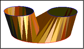
Note: To see all of the steps performed in this section, run
_03a_bifurcation.tcl. You need to click Apply on any forms presented.
Task: Use one segment to two segments to model a bifurcation.
- Click Reset graphics .
- Open mod4.dtm in Graphics.
- Choose Display > Hide everything.
- Choose Display > Strings > With string numbers.
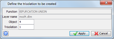
- Enter the information as shown, and click Apply.
- Choose Solids > Triangulate > One segment to two segments.
- Enter the information as shown, and click Apply.
- Enter the information as shown, and click Apply.
- Click string 14.
- Enter the information as shown, and click Apply.
- Click the left child segment of string 15.
- Enter the information as shown, and click Apply.
- Click the right child segment of string 15.
- Choose Display > All layers.
- Click Zoom to data extents
 .
. - Save as mod4.dtm.
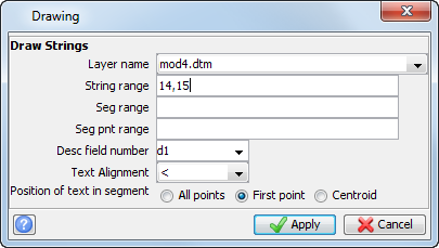
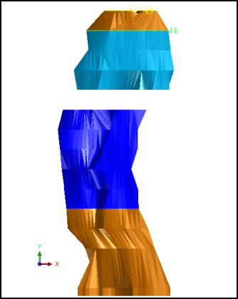
Note: String 14 will be the parent segment and the two segments of string 15 will be the child segments.
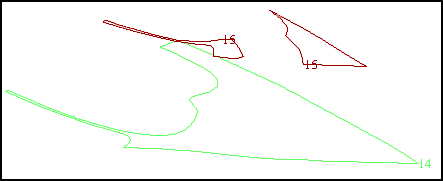
You are prompted to select the parent segment.
You are then prompted to state whether the first child is a (S)egment or a (P)oint.
A prompt will appear asking whether the second child is a (S)egment or (P)oint.
The following image is displayed.
Note: To see all of the steps performed in this section, run
_03b_bifurcation_on_model.tcl. You need to click Apply on any forms presented.
Task: Perform bifurcation using the triangulate shape tool
- Start the triangulation.
- Open bifurc4.str in Graphics.
- Zoom out.
- On the Tools toolbar, click Triangulate Shape
 .
. - Click the start point as shown.
- Select the line of bifurcation as shown, clicking the points indicated with green arrows.
- Continue selecting the shape by following the left child node as shown and returning to the start point.
- Select the points as shown, finishing at the point where you started.
- Select the points as shown, finishing at the point where you started.
- Select the points as shown, finishing at the point where you started.
- You have now finished triangulating the bifurcation using the Triangulate Shape tool.
- From the Select tool drop-down on the Tools toolbar, click Select Segment/Trisolation.
- Click the parent segment to select it, and then right-click to display a shortcut menu.
- Choose Triangulate.
- Click the left child segment to select it, and then right click to display a popup menu.
- Choose Triangulate.
- Click the right child segment to select it, and then right click to display a popup menu.
- Choose Triangulate.
- Save the solid model as bifurc4finished.dtm.
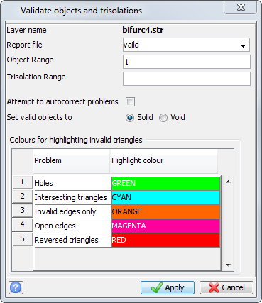
- Choose Solids > Validation > Validate object/trisolation.
- Enter the information as shown, and click Apply.
- Open the file valid1.not in a text editor.
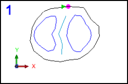
Notice that the point is highlighted as you hover over it, or if you click the point.
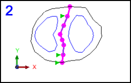
 Tip: When selecting the points in a segment, Surpac chooses the shortest path between two points. This sometimes gives unwanted results by either skipping intermediate points or flipping to the opposite side of the segment. This is easily fixed by clicking on the intermediate points, which anchors the point by forcing Surpac to select it.
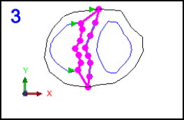
After the shape is joined up by clicking at the start point, that part of the model is triangulated as shown.
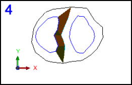
You have now triangulated the right side of the left child and next you will triangulate the left side of the left child.
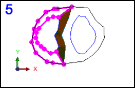
You have now finished the triangulation for the left child
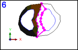
You have now triangulated the left side of the right child.
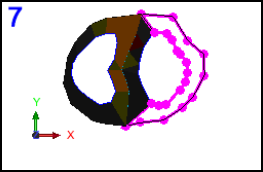
The bifurcation example is displayed.
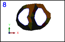
Next you will use data-centric mode to triangulate inside the parent and child segments to close the solid.
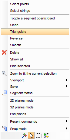
Notice that the parent segment has become closed.
The closed solid is displayed.
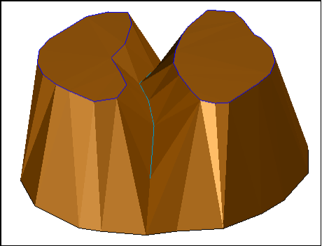
The Solids Modelling Validation report is displayed.

You can see that from the report that the solid is closed and validated.