Triangulating a fault
Task: Triangulate a fault by draping strings and triangulating
Preparing the data:
- Click Reset graphics
 .
. - Open fault1.str in Graphics.
- Open mod6.dtm in Graphics.
- Choose Display > Hide surface/solid.
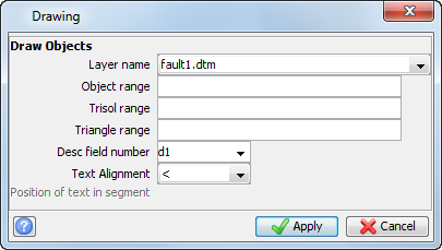
- Enter the information as shown, and click Apply.
- Choose Display > Strings > With string numbers.
- Enter the information as shown, and click Apply.
- Rotate the data as shown to view the fault plane.
- Choose File > Save > string/DTM.
- Enter the information as shown, and click Apply.
- Choose File > Save > string/DTM.
- Enter the information as shown, and click Apply.
- Click Reset graphics .
- Open s1.str, n1.str, and fault1.str in Graphics.
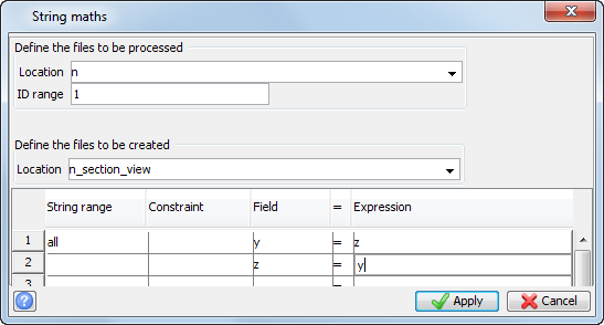
- Choose File tools > String maths.
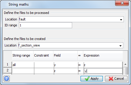
- Enter the information as shown, and click Apply.
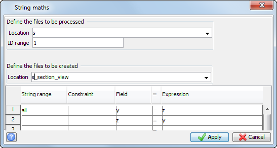
- Choose File tools > String maths.
- Enter the information as shown, and click Apply.
- Choose File tools > String maths.
- Enter the information as shown, and click Apply.
- Click Reset graphics .
- Open n_section_view1.str, s_section_view1.str, and f_section_view1.str in that order in Graphics.
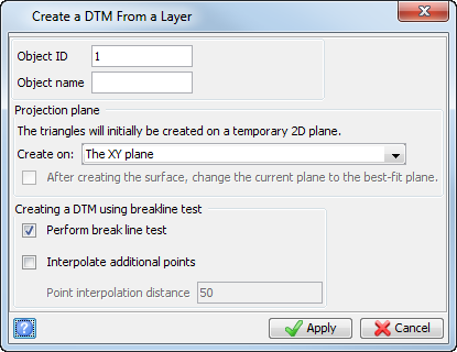
- Choose Surfaces > Create DTM from Layer.
- Enter the information as shown, and click Apply.
- Save as f_section_view.dtm.
The section strings and fault are displayed.
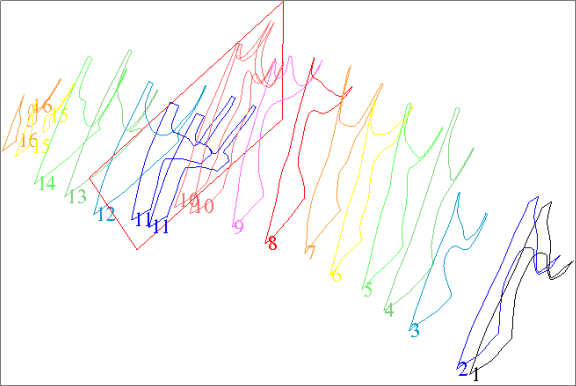
The string fault1.str represents the fault through this area. Ideally, you need two shapes that coincide with the fault on either side of the fault. The following steps illustrate one way of doing this.
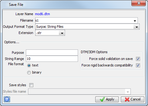
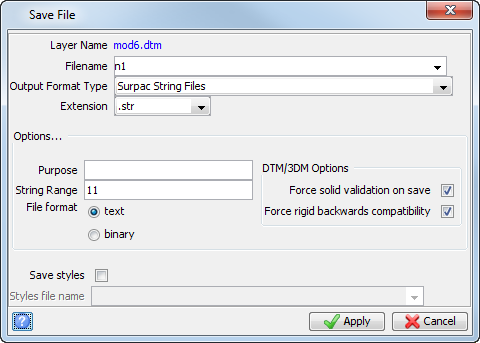
The plan view of the fault is displayed.
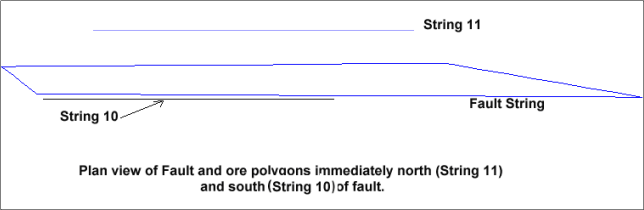
You now need to press these strings onto the surface of the fault.
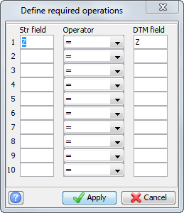
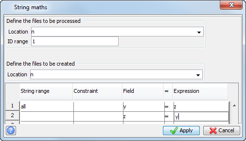
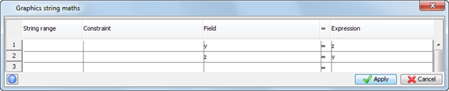
This function works only on Z or Description fields, therefore you will need to swap your Y and Z coordinates to make this function work correctly (for example, go to section view).
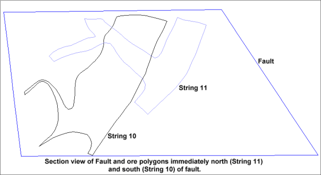
The fault with Ore Polygons is displayed.
 Note: To see all of the steps performed in this task, run
_04b_triangulate_fault_data_preparation.tcl. You need to click Apply on any forms presented.
Note: To see all of the steps performed in this task, run
_04b_triangulate_fault_data_preparation.tcl. You need to click Apply on any forms presented.
Draping the strings and triangulating:
- Choose Surfaces > DTM file functions > Drape strings over a DTM.
- Enter the information as shown, and click Apply.
- Enter the information as shown, and click Apply.
- Click Reset graphics .
- Open f_section_view1.dtm in Graphics.
- Open s_section_view1.str, which contains string 10 in Graphics.
- Rotate the view so you can clearly see the string.
- Choose Surfaces > Drape string over DTM.
- Click string 10.
- Enter the information as shown, and click Apply.
- Save as s1.str.
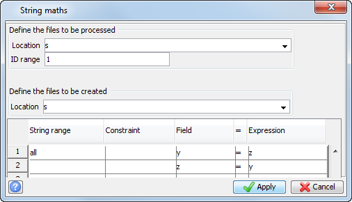
- Choose File tools > String maths, and swap n1.str (string 11) back to plan view as shown.
- Choose File tools > String maths, and swap s1.str (string 10) back to plan view as shown.
- Click Reset graphics .
- Open s1.str in Graphics.
- Open n1.str, appending it to the same layer.
- Open and append mod6.dtm.
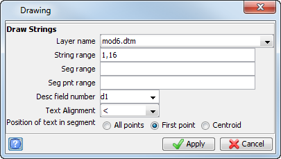
- Choose Display > Hide everything.
- Choose Display > Strings > With string numbers.
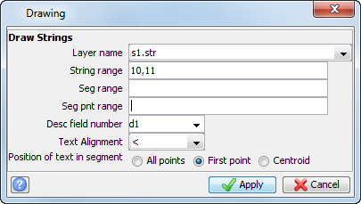
- Enter the information as shown, and click Apply.
- Zoom in and adjust the view as necessary to see the data clearly.
- Choose Solids > Triangulate > Between segments.
- Enter the information as shown, and click Apply.
- Click string 10, segment 1 and then string 10, segment 2.
- Press ESC.
- Choose Solids > Triangulate> Between segments.
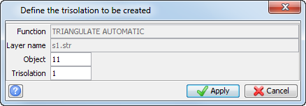
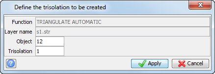
- Enter the information as shown, and click Apply.
- Click string 11, segment 1 and string 11, segment 2.
- Press ESC.
- Save as mod6.dtm.
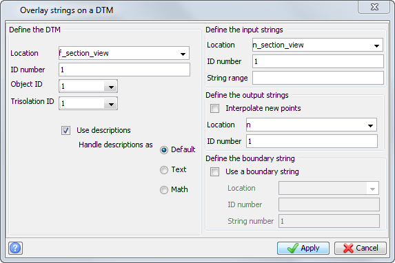
The operation to be performed is Z = Z and this is the default operation displayed.
Strings can also be pressed onto a DTM by opening the DTM into one layer and the string file to be pressed into another. You will now press string 10 in file s1.str against the fault plane.
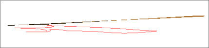
You are prompted to select the string to be draped over the DTM.
You will be prompted to select the layer that contains the DTM file.

Note: You will see that the string is pressed onto the DTM surface. New points will be interpolated into the pressed string so that the strings are pressed perfectly against the DTM
surface.
Now you are ready to incorporate the newly created strings into your solid model.
Note: Hold the
CTRL key while dragging
n1.str into Graphics.
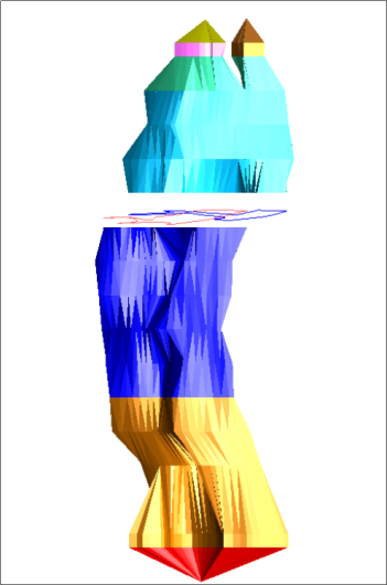
You should see that the two string segments are coincident along the plane of the fault.
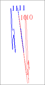
Two string segments are displayed.
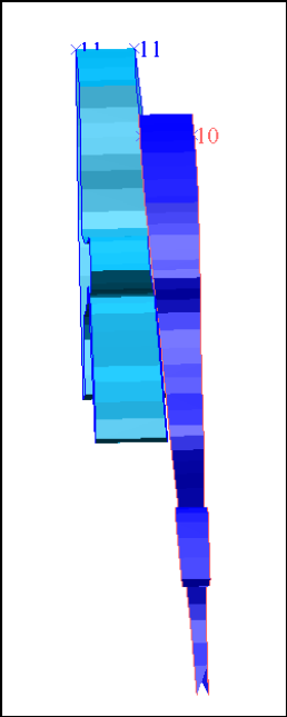
The following image is displayed.
Note: If you want to run manually through the material again, you will need to copy
original_mod6.dtm, and save it as
mod6.dtm.
Note: To see all of the steps performed in this task, run
_04c_draping_strings_and_triangulating_fault.tcl. You need to click Apply on any forms presented.
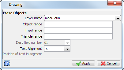
Task: Triangulate a fault by extruding and clipping
- Click Reset graphics .
- Open fault1.dtm in Graphics.
- Open mod5.dtm in Graphics.
- In the Layer pane, right click on fault.dtm and select Layer maths.
- Enter the information as shown, and click Apply.
- In the Layer pane, right click on mod5.dtm and select Layer maths.
- Enter the information as shown, and click Apply.
- Click Zoom to data extents
 .
. - Click Section view
 .
. - Choose Solids > Triangulate > Extrude and triangulate a segment.
- Click the segment below the fault in Graphics.
- Enter the information as shown, and click Apply.
- Choose Solids > Triangulate > Extrude and triangulate a segment.
- Click the segment above the fault in Graphics.
- Enter the information as shown, and click Apply.
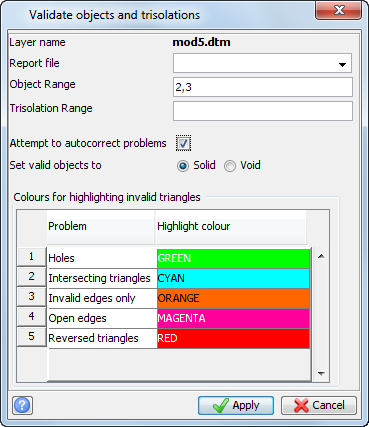
- Choose Solids > Validation > Validate object/trisolation.
- Enter the information as shown, and click Apply.
- Choose Solids > Solids tools > Clip solid below a DTM.
- Enter the information as shown, and click Apply.
- Click on the segment of the southern solid that spans the fault in Graphics.
- Click the fault in Graphics.
- Choose Display > Surface or Solid.
- Enter the information as shown, and click Apply.
- Choose Solids > Solids tools > Clip solid above a DTM.
- Enter the information as shown, and click Apply.
- Click on the segment of the northern solid that spans the fault in Graphics.
- Click the fault in Graphics.
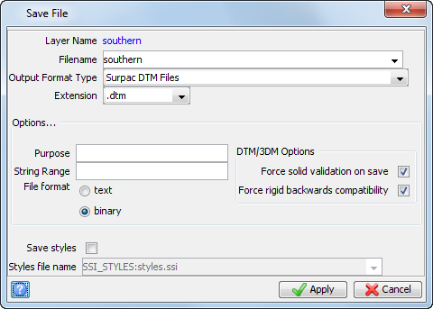
- In the Layers pane, right-click the southern layer, and select Save layer.
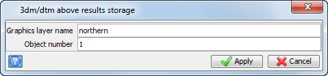
- Enter the information as shown, and click Apply.
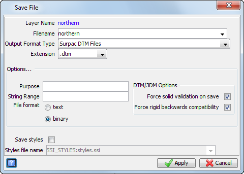
- In the Layers pane, right-click the northern layer, and select Save layer.
- Enter the information as shown, and click Apply.
- Click Reset graphics .
- Open southern.dtm in Graphics.
- Append northern.dtm to the same layer by holding CTL and dragging the file into Graphics.
- In the Layers pane, right-click on southern.dtm and select Layer maths.
- Enter the information as shown, and click Apply.
- Append mod5.dtm to the same layer by holding CTL and dragging the file into Graphics.
- Save the combined data as mod6.dtm.
- Click Reset graphics .
- Open mod6.dtm in Graphics.
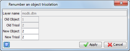
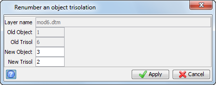
- Choose Solids > Edit trisolation > Renumber.
- Click the solid below the fault in Graphics.
- Enter the information as shown, and click Apply.
- Click the solid above the fault in Graphics.
- Enter the information as shown, and click Apply.
- Save mod6.dtm.
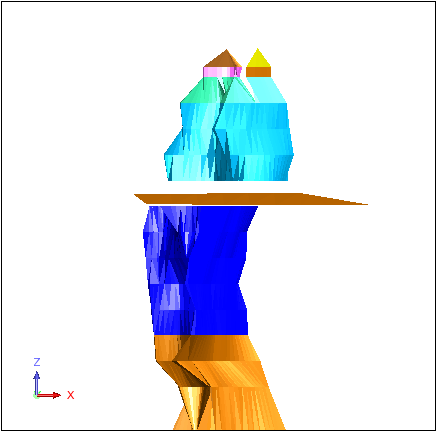
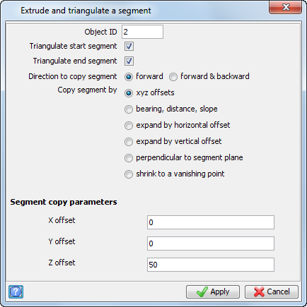
The section is extended above the fault.
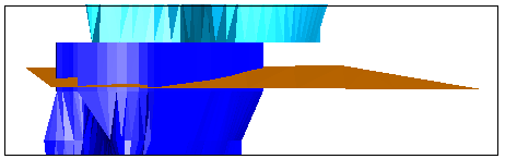
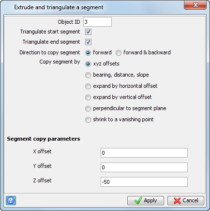
The section is extended below the fault.
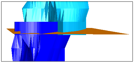
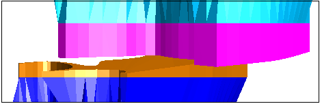
The section of the segment below the fault DTM is retained.
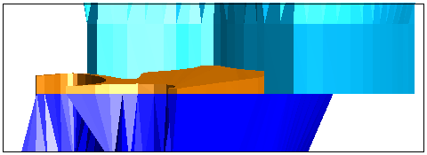
The section of the segment above the fault DTM is retained.