


Solids concepts
What is a solid model?
A solid model is a three-dimensional triangulation of data. For example, a solid object can be formed by stitching triangles around strings that often represent sections through the shape being modelled.
Solid models are based on the same principles as digital terrain models (DTMs). Solid models use triangles to link polygonal shapes together to define a solid object or a void.
The resulting shapes may be used for:
- visualisation
- volume calculations
- extraction of slices in any orientation
- intersection with data from the geological database module
A DTM is used to define a surface. Creating a DTM is automatic. Triangles are formed by connecting groups of three data points together based on their spatial location in the X - Y plane.
The drawback of this type of model is that it cannot model a structure that may have foldbacks or overhangs, for example:
- geological structures
- stopes
- underground mine workings, such as declines, development drives, and draw points
A solid model is created by forming a set of triangles from the points contained in a string. These triangles may appear to overlap when you are in plan view, but they do not overlap or intersect when the third dimension is considered. The triangles in a solid model may completely enclose a structure.
Creation of solid models can be more interactive than the creation of DTMs, although there are many tools in Surpac that can automate the process.
Terminology
A solid model is made up of a set of non-overlapping triangles. These triangles form objects that have a numeric identifier between 1 and 32000. Objects represent discrete features in a solid model.
However, features such as ore bodies can consist of discrete parts, and you might want to give these parts the same object number to indicate that they are from the same structure. To identify each part separately, you can give each discrete part a different trisolation number, while keeping the same object number. A trisolation is a discrete part of a solid or surface. Like objects, trisolations are identified by a positive integer. Trisolations should be physically separated from each other. They should not share any points with other trisolations.
You can refer to all of the parts of a solid model using their object and trisolation numbers.
 Example: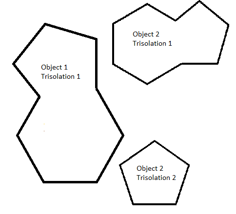
An object trisolation may be open or closed. A trisolation is open if there is a gap in the set of triangles that make up the trisolation. An object may contain both open and closed trisolations.
The reasons for treating objects as open or closed are:
- a closed object can have its volume determined directly by summing the volumes of each of the triangles to an arbitrary data plane
- a closed object always produces closed strings when sliced by a plane
- a closed object could be used as a constraint in the Block Modelling module
- an open object cannot provide the same capabilities; when sliced by a plane the strings it produces may be open or closed or both
Solids files
Solid models are stored in the same way as DTMs, in two ASCII text files, one .str and one .dtm.