


Modelling underground data
Task: Model underground data
- Click Reset graphics
 .
. - Open lev200.str in Graphics.
- Choose Display > Strings > With string numbers.
- Enter the information as shown, and click Apply.
- Choose File > Save > string/DTM.
- Enter the information as shown, and click Apply.
- Choose File > Save > string/DTM.
- Enter the information as shown, and click Apply.
- Click Reset graphics .
- Open back1.str in Graphics.
- Choose Inquire > Segment Properties, and click on each segment to check its direction.
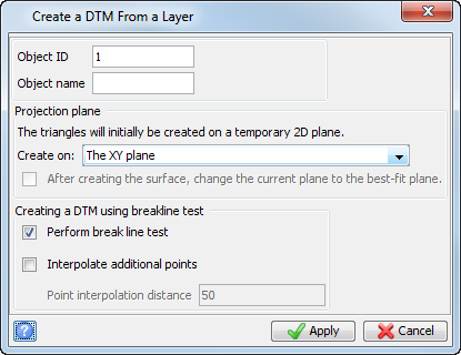
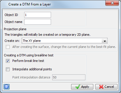
- Choose Surfaces > Create a DTM from layer.
- Enter the information as shown, and click Apply.
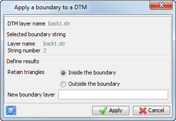
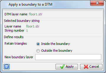
- Choose Surfaces > Clip or intersect DTMs > Clip DTM with string.
- Click string 2 (the pillar and wall pickup string).
- Enter the information as shown, and click Apply.
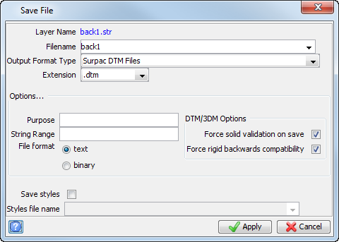
- Choose File > Save > string/DTM.
- Enter the information shown, and click Apply.
- Click Reset graphics .
- Open floor1.str in Graphics.
- Choose Surfaces > Create DTM from layer.
- Enter the information as shown, and click Apply.
- Choose Surfaces > Clip or intersect DTMs > Clip DTM with string
- Click string 1.
- Enter the information as shown, and click Apply.
- Save floor1.dtm.
- Click Reset graphics .
- Open and append back1.dtm and floor1.dtm into the main graphics layer.
- Choose Solids > Edit trisolation > Renumber.
- Click back1.dtm.
- Enter the information as shown, and click Apply.
- Click floor1.dtm.
- Enter the information as shown, and click Apply.
- Press ESC.
- Save the file as drives1.dtm.
- Click Reset graphics .
- Open drives1.dtm in Graphics.
- Choose Display > Strings > With string numbers.
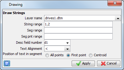
- Enter the information as shown, and click Apply.
- Choose Solids > Triangulate > Between segments.
- Enter the information as shown, and click Apply.
- Following the prompts from the function line, click first the outer back string, and then the outer floor string
- Press ESC.
- Choose Solids > Triangulate > Between segments.
- Enter the information as shown, and click Apply.
- Following the prompt from the function line, click first the top string of the pillar, and then the bottom string of the pillar.
- Press ESC.
- Save drives1.dtm.
- Choose Solids > Validation > Validate object/trisolation.
- Enter the information as shown, and click Apply.
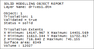
- Choose Solids > Solids tools > Report volume of solids.
- Enter the information as shown, and click Apply.
Floor and back strings are displayed.
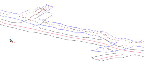
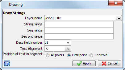
 Note: In this case, the string numbers for the backs are 2 and 30003 and for the floor are 1 and 1001. String 30003 is a spot height string. You will need to create separate DTM files for the backs and the floors.
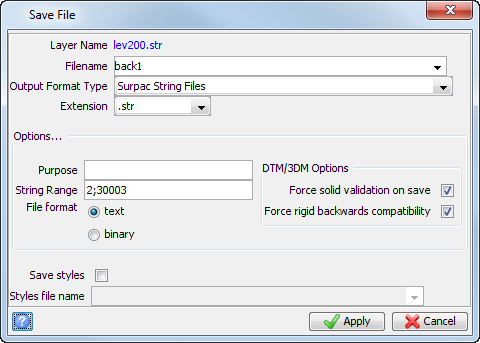
Note: This creates a string file containing just the back strings. Notice that the separator for the string range is a semicolon.
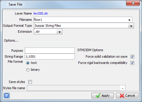
Note: This will create a string file containing just the floor strings. Notice that the separator for the string range is a semicolon.
Strings 2 and 30003 are displayed.
The pillar segment is anti-clockwise within an enclosing outer boundary segment that is clockwise.
You are prompted to select the trisolation, then a string.
The underground spot height string is displayed.
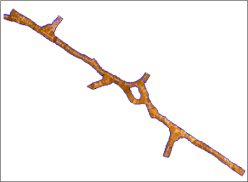
Note: The DTM has been clipped correctly because of the string directions set for the walls and pillars.
You are prompted to select the trisolation, and then a string.
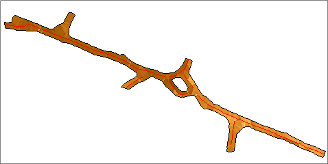
The underground backs are displayed.
Now that both clipped DTMs have been created, you will stitch together the sides to create a closed, valid solid model.
Note: To append the DTMs to the same layer, hold down the
CTRL key and drag the files into Graphics.
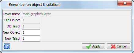
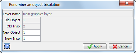
Notice that the old trisolation number is 2 in this case.
Note: When performing solids modelling, it is good practice to save your work regularly.
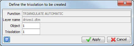
Repeat the process for the pillar.
The underground result is displayed.
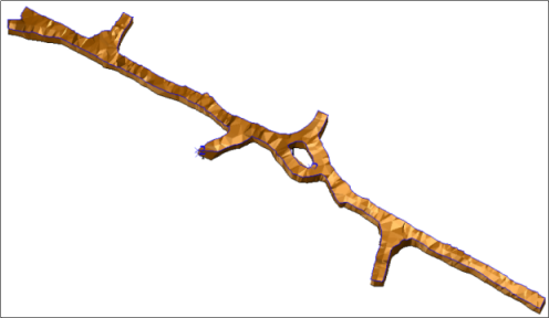
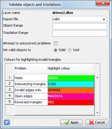
The validation report is displayed.

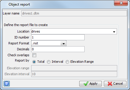
The Solid Modelling Object report is displayed.
Note: To see all of the steps performed in this task, run
_15_create_underground_model.tcl. You need to click Apply on any forms presented.