


Intersecting solids and DTM surfaces
Intersecting solids
Task: Perform solids union
- Click Reset graphics
 .
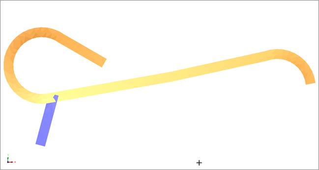
. - Open decline1.dtm in Graphics.
- Open crosscut1.dtm in Graphics.
- Click Zoom all
 .
. - Choose Solids > Solids tools > Union solids.
- Enter the information as shown, and click Apply.
- Follow the prompts and click each of the solids.
- The order you use to select the solids is not important. Surpac will union the solids in the same way regardless of the order they are selected.
- After the solids are unioned, the previous objects are erased from Graphics , and the active layer is the layer you specified, with the unioned solid displayed.
- The solid is not saved in the layer until you use the save function.
- Choose View > Surface view options > Hide triangle edges.
- The triangle edges are displayed, more effectively displaying the union.
- Zoom in to the area of contact, and confirm the result of the union.
- Choose View > Surface view options > Hide triangle faces.
The solids are displayed.
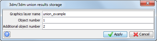
 Note: The layer name cannot be the same as any existing layer. The new layer will contain the new solid.
Note:
The union of the drives is displayed.
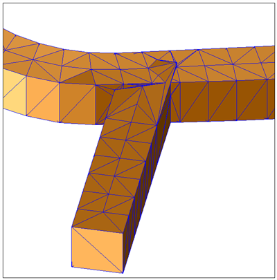
The union triangles are displayed and you can see the way that the underlying strings have been changed.
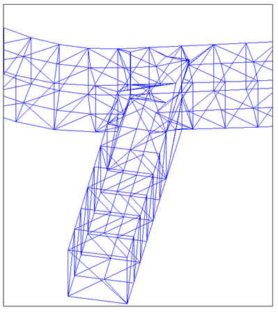
Note: To see all of the steps performed in this task, run
_08a_solids_union.tcl. You need to click Apply on any forms presented.
Task: Perform intersection of solids
- Click Reset graphics .
- Open lev1.dtm in Graphics.
- Open stope1.dtm in Graphics.
- Click Zoom all.
- Choose Solids > Solids tools > Intersect solids.
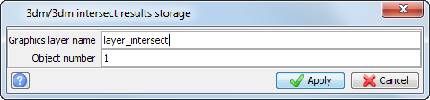
- Enter the information as shown, and click Apply.
- Follow the prompts and click each of the solids in turn.
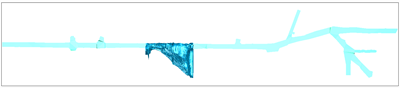
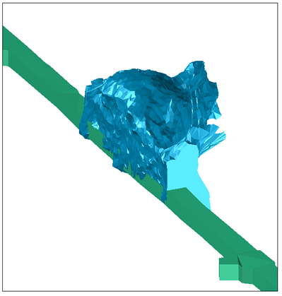
These solids represent a stope and a development drive as shown.
Note: The order in which you select the solids is not important.
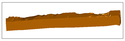
The active layer is now the layer you specified with the intersected solid displayed. The result is the area of the decline that fell within the stope.
Note: To see all of the steps performed in this task, run
_08b_solids_intersection.tcl. You need to click Apply on any forms presented.
Task: Perform outersection of solids
- Click Reset graphics .
- Open lev1.dtm in Graphics.
- Open stope1.dtm in Graphics.
- Click Zoom all .
- Choose Solids > Solids tools > Outersect solids.
- Enter the information as shown, and click Apply.
- Follow the prompts and click each of the solids - first the ore body and then the decline.
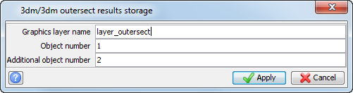
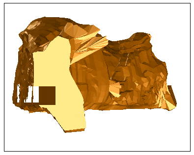
In this case, the order of selection is important. The outersected solid must be selected first, while the outersecting solid (that is, that one that will cut into the outersected solid) is selected second.
The active layer is now the layer you specified, with the solid displayed. The result is the original solid body with those areas that were common with the decline removed.
Note: To see all of the steps performed in this task, run
_08c_solids_outersection.tcl.
You need to click Apply on any forms presented.
Task: Clip a solid above a DTM
- Click Reset graphics .
- Open pit4.dtm in Graphics.
- Open ore4.dtm in Graphics.
- Choose Solids > Solids tools > Clip solid above a DTM.
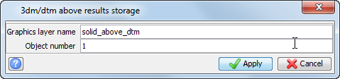
- Enter the information as shown, and click Apply.
- Click the ore solid and then click the pit.
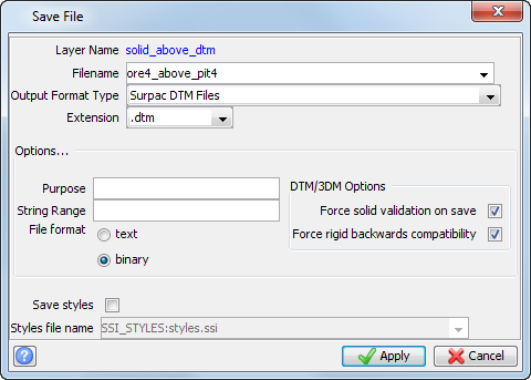
- To save the result, choose File > Save > string/DTM.
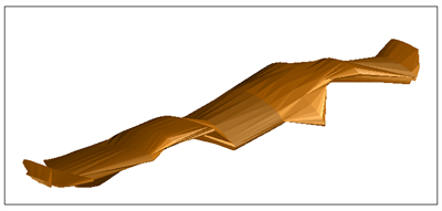
The ore body is displayed.
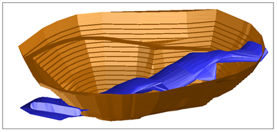
The section of the ore body that is above the pit is displayed.
Note: To see all of the steps performed in this task, run
_08d_solid_above_dtm.tcl. You need to click Apply on any forms presented.
Task: Clip a DTM outside a solid
- Click Reset graphics .
- Open pit4.dtm in Graphics.
- Open ore4.dtm in Graphics.
- Choose Solids > Solids tools > Clip DTM outside a solid.
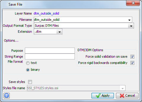
- Enter the information as shown, and click Apply.
- Click the orebody, and then click the pit.
- To save the result, choose File > Save > string/DTM.
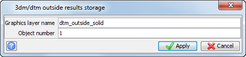
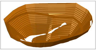
The active layer is now the layer you specified, and the pit cut by the ore body displayed.
Note: To see all of the steps performed in this task, run
_08e_dtm_outside_solid.tcl. You need to click Apply on any forms presented.
Intersecting DTM surfaces
Task: Perform upper triangles intersection of two DTMs
- Click Reset graphics .
- Open topo2.dtm in Graphics.
- Open dump1.dtm in Graphics.
- Choose Surfaces > Clip or intersect DTMs > Upper triangles of 2 DTMs.
- Enter the information as shown, and click Apply.
- Follow the prompts and click on each DTM.
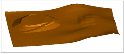
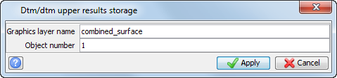
Note: The order in which you select the DTMs is not important.
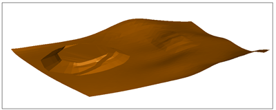
The active layer is the layer you specified, with the DTM displayed. The result is the waste stockpile surface incorporated into the topographic surface.
Note: To see all of the steps performed in this task, run
_08f_upper_triangles_of_2dtm.tcl. You need to click Apply on any forms presented.
Task: Perform lower triangles intersection of two DTMs
- Click Reset graphics .
- Open topo2.dtm in Graphics.
- Open pit2.dtm in Graphics.
- Choose Surfaces > Clip or intersect DTMs > Lower triangles of 2 DTMs.
- Enter the information as shown, and click Apply.
- Follow the prompts and click on each DTM.
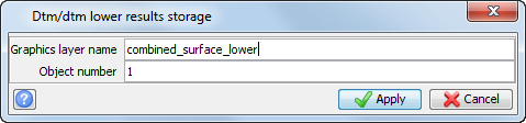
Note: The order in which you select the DTMs is not important.
The pit below the topography is displayed.
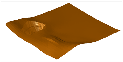
Note: To see all of the steps performed in this task, run
_08g_lower_triangles_of_2dtm.tcl. You need to click Apply on any forms presented.
Task: Create a solid by intersecting two DTMs
- Click Reset graphics .
- Open topo2.dtm in Graphics.
- Open pit2.dtm in Graphics.
- Choose Surfaces > Clip or intersect DTMs > Create solid by intersecting 2 DTMs.
- Enter the information as shown, and click Apply.
- Follow the prompts and click the upper DTM, and then the lower DTM.
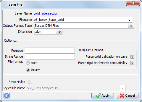
- Choose File > Save > string/DTM.
- Enter the information as shown, and click Apply.
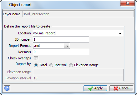
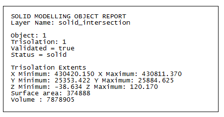
- To determine the volume of the pit below the topography, choose Solids > Solids tools > Report volume of solids.
- Enter the information as shown, and click Apply.
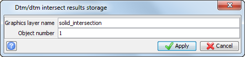
Note: The upper DTM (topography) must be selected first.
The active layer is the layer you specified, with the solid displayed. The result is a solid representing the material that will need to be removed from the designed pit.
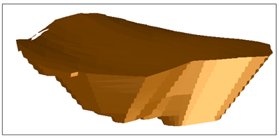
The solid modelling object report is displayed.
Note: To see all of the steps performed in this section, run
_08h_create_solid_intersecting_2dtms.tcl. You need to click Apply on any forms presented.