


Creating sections
Task: Create sections using the interactive method
- Click Reset graphics
 .
. - Open mod12.dtm in Graphics.
- Choose Solids > Solids tools > Create sections.
- Click Digitise to use your mouse for defining the axis.
- Click a start point below the bottom centre of the ore body and drag the pointer vertically to the end point of the axis line above the solid.
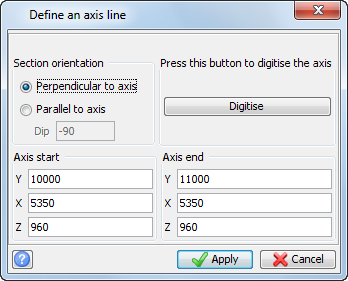
- Enter the information as shown, and click Apply.
- Enter the information as shown, and then Apply.
- Click and drag the pointer to move the object in 3D space and view how the slices relate to the solid.
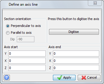
The solid with a centreline is displayed.
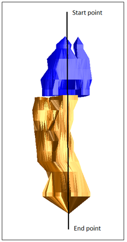
 Note: When you create the axis, the Define and axis line form is displayed with the real world coordinates of your axis line. You can adjust the coordinates manually using the digitised axis start and end points as a guide. In this case, the Eastings and elevations for the axis line are kept the same to produce slices that are oriented as Northings.
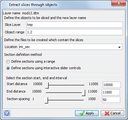
Note: To display your slices in real time, click Interactive slider controls. The slide controls enable you to adjust the start and end points of your axis, and the distance between slices. Move the slide controls up and down to see the effect of your changes. When you click Apply, the slices are taken using the values in the boxes on the right side of the slider bar. You can also type the values into these boxes manually.
The solid object with slices is displayed.
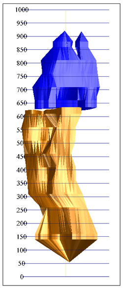
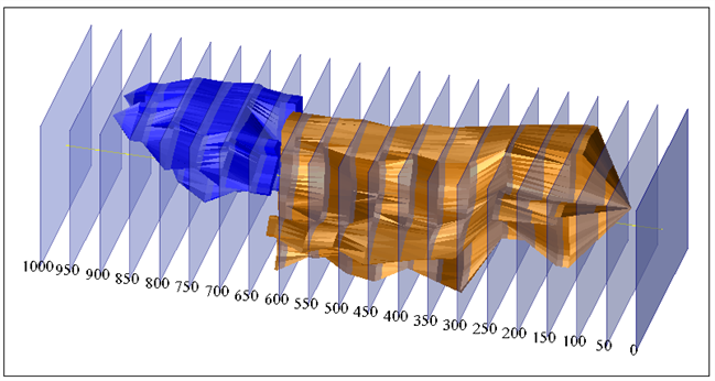
Note: To see all of the steps performed in this task, run _10a_slice_objects_interactive.tcl. You need to click Apply on any forms presented.
Task: Create sections by range
- Click Reset graphics .
- Open mod12.dtm in Graphics.
- To determine the Maximum and Minimum Y, X, and Z coordinates, choose Inquire > Report layer extents.
- Choose Solids > Solids tools > Create sections.
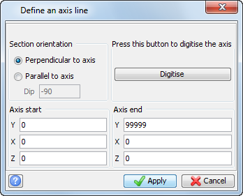
- Enter the information as shown, and click Apply.
- Enter the information as shown, and click Apply.
The data shown in the window extends from 10055 North to 10920 North. You can slice the objects by defining a north-south axis.
For this task you will slice this model on Northings (Y). To do this you will define a vertical axis.
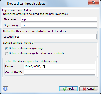
The solid with sections is displayed.
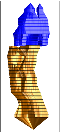
Note: To see all of the steps performed in this task, run _10b_slice_objects_by_range.tcl. You need to click Apply on any forms presented.
Task: Create sections using a centre line
- Click Reset graphics .
- Open stope2.dtm in Graphics.
- Open cl2.str in Graphics.
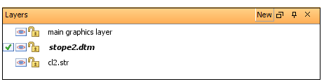
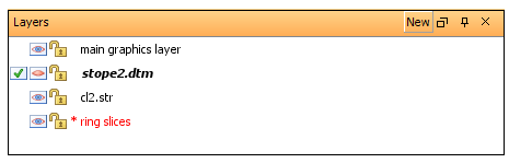
- In the Layers pane, make stope2.dtm the active layer.
- Choose Solids > Solids tools > Section using centre line.
- Click the start and end points of your centre line, as shown on the previous image.
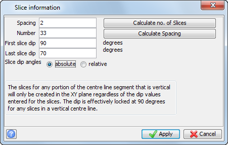
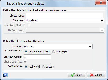
- Enter the information as shown, and click Apply.
- Enter the information as shown, and click Apply.
- In the Layers pane, make stope2.dtm invisible.
When slicing a solid, the centre line string and the objects that are sliced can be in separate layers or in the same layer. To view the sections in Graphics, it is usually clearer if you use separate layers.
Note: If the centre line string and the objects are in separate layers, the layer containing the solids must be the active layer.
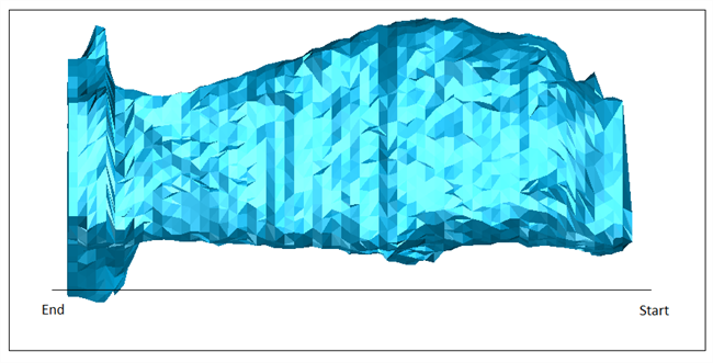
The ring slice is displayed.
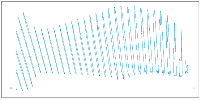
The slices start at 90 degrees and the last slice is at 70 degrees.
Note: To see all of the steps performed in this task, run _10c_centre_line_slice.tcl. You need to click Apply on any forms presented.
Task: Create sections using quick planes
- Click Reset graphics .
- Open stope2.dtm.
- Choose Planes > Quick planes.
- Enter the information as shown, and click Apply.
- Click the Planes tab, and click the Toggle auto-hide button to pin the Planes panel to the interface.
- Expand the QuickPlanes_1 group.
- Press F12 to move to the next plane, and F11 to move to the previous plane.
- Choose Planes > Save section to string files.
- Enter the information as shown, and click Apply.
- Click Reset graphics .
- Open 4680n_section.str.
- Open stope2.dtm.
- Right-click to the right of the toolbars and choose Toolbars > Scale and transparency.
- Set the Transp. slider to 80%.
- Rotate the data in Graphics so that you can see the string outline at plane 6480N on the DTM.
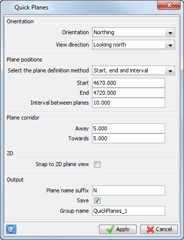
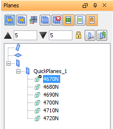
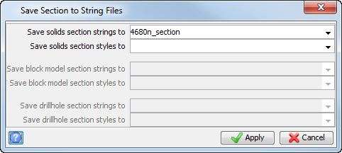
The plane cross sectional outline is saved to the string file specified.
The Z scale and Transp. sliders appear under the current toolbars.

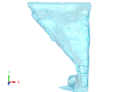
Note: To see all of the steps performed in this task, run _10d_section_with_quick_planes.tcl. You need to click Apply on any forms presented.