


Designing roads using string editing tools
In this chapter, you will learn how to create a road design by using simple string editing tools available in the Core Module.
Task: Design a road using CURVE END
In this task, you will learn how to use the function CURVE END to create a road design containing a simple horizontal curve with transition curves on either side.
- Click Reset graphics
 .
. - Open pit&dump.str in Graphics.
- Open pit_dump_road_centreline.str in Graphics.
- Zoom out to view the data as shown.
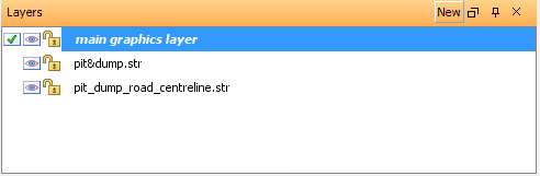
- In the Layers pane, double-click main graphics layer to set it as the default layer.
- Click the design string button
 on the Status bar.
 - Enter the information as shown, and click Apply.
- Choose Create > Points > By angle.
- Click Point 1 and then Point 2, as shown.
- Enter the information as shown, and click Apply.
- Click the same two points again.
- Enter the information as shown, and click Apply.
- Press ESC.
- Choose Create > Curve at segment end.
- Click Point 1 and then Point 2, as shown.
- Enter the information as shown, and click Calculate.
- After the transition lengths are calculated (as shown), click Apply.
- Press ESC.
-
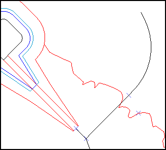
Zoom into the view as shown.
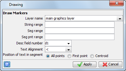
- Choose Display > Point > Markers.
- Enter the information as shown, and click Apply.
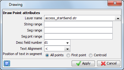
- Choose Display > Point > Attributes.
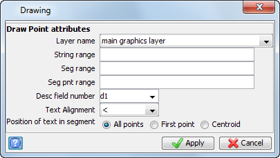
- Enter the information as shown, and click Apply.
- Choose Inquire > Bearing and distance between 2 points.
- Click Point 1 and then click Point 2, as shown.
- Press ESC.
- Choose Create > Points > By bearing.
- Click the end of the curve (Point 2 in the previous image).
- Enter the information as shown, and click Apply.
- Press ESC.
- Click the design string button
 on the Status bar.
 - Enter the information as shown, and click Apply.
- Choose Design > Underground tools > Room & pillar from centrelines.
- Enter the information as shown, and click Apply.
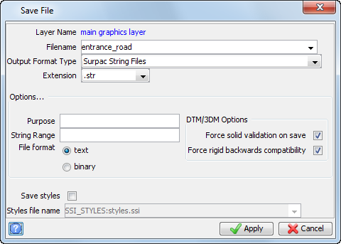
- Click Save
 .
. - Enter the information as shown, and click Apply.
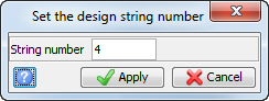
Design string number 4 will be used for the road centreline.
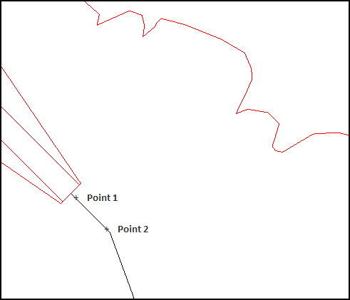
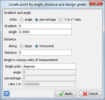
This creates the start point for the new road, which is at the same coordinates as the point near the second point selected.The point is created in string 4.
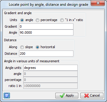
This creates the second point of the road centreline, as shown.
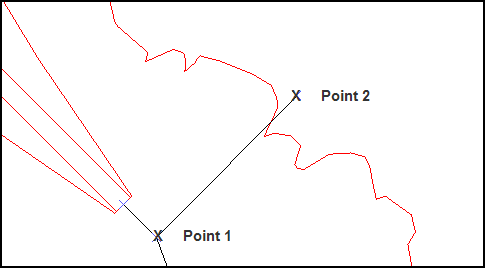
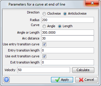
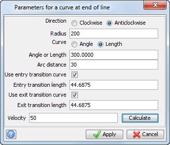
 Note: Points have been created every 30 metres along the arc
length to approximate the
curve.
Note: Points have been created every 30 metres along the arc
length to approximate the
curve.
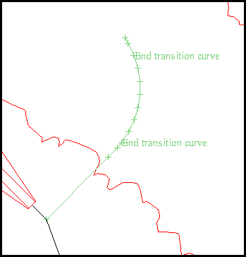
Note: The points where the transition curve ends, and the
simple curve begins have the description "End transition curve".
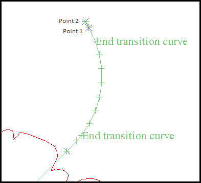
The bearing from Point 1 to Point 2 is displayed in the message window, as shown.

Next, the road centreline will be extended at this bearing.
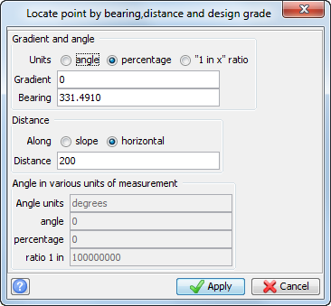
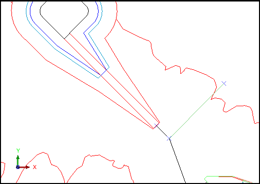
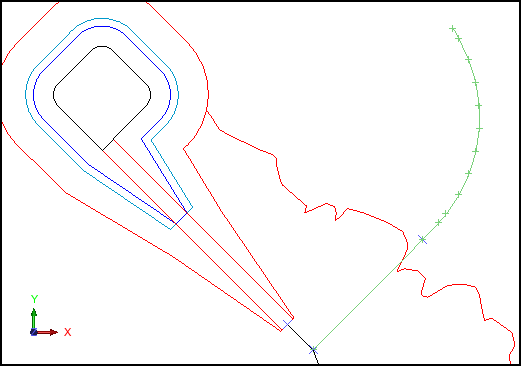
The road centreline is extended horizontally 200 metres at the bearing of 331 degrees, 49 minutes, 10 seconds, as shown.
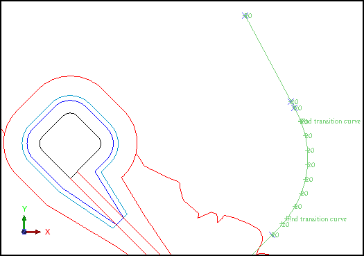
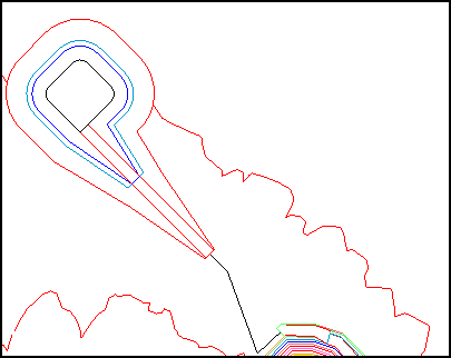
The centreline design is complete. The next step is to create the road outline.
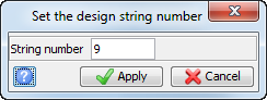
The design string number of 9 will be used for the road outline.
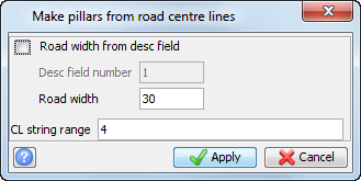
The road outline is created, as shown.
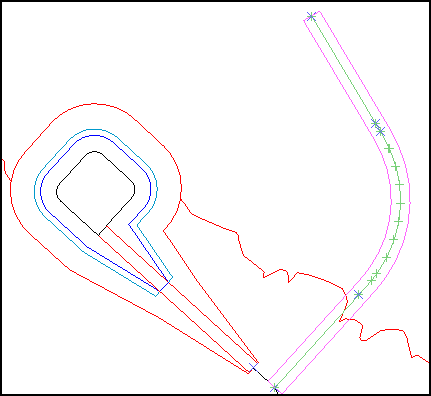
Note: The function
MAKE PILLARS is used to create the
road outline in this example.
Note: To see all the steps performed in this section, run
1a_curve_end.tcl. You need to click
Apply on any forms presented.
Task: Design a road using CURVE TANGENT
In this task, you will learn how to use the function CURVE TANGENT to create a road design from a centreline string that contains an inflection point.
- Click Reset graphics.
- Open pit&dump.str in Graphics.
- Open pit_dump_road_centreline.str in Graphics.
- Choose Display > Point > Numbers.
- Enter the information as shown, and click Apply.
- From the mode selector, choose Insert point mode.
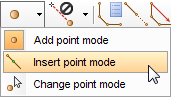 Note: The insert mode will result in points inserted within
the centreline string when the curve is created.
Note: The insert mode will result in points inserted within
the centreline string when the curve is created. - Choose Create > Curve from tangents.
- Click Point 1 and then Point 2.
Note: The line connecting points 1 and 2 define the first tangent.
- Click Point 2 (again) and then Point 3.
Note: The line connecting points 2 and 3 define the second tangent.
- Enter the information as shown, and click Apply.
- Press ESC.
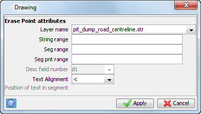
- Choose Display > Hide point > Attributes.
- Enter the information as shown, and click Apply.
- Click the design string button
on the status bar.
- Enter the information as shown, and click Apply.
- Choose Design > Underground tools > Room & pillar from centrelines.
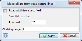
- Enter the information as shown, and click Apply.
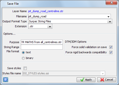
- Click Save .
- Enter the information as shown, and click Apply.
Zoom into the view as shown.
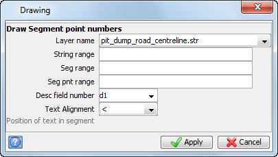
The point numbers are displayed, as shown.
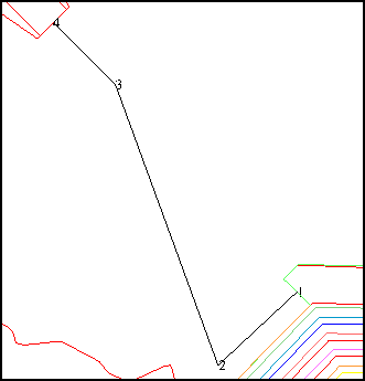
Note: It is not necessary to display the point numbers.
This is done in this example to identify the points to select.
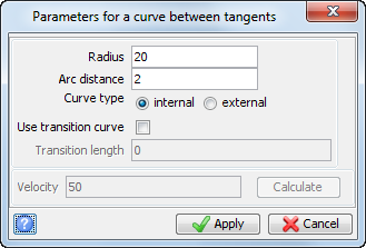
Note: In this example, a simple curve is created because you have not selected Use transition curve.
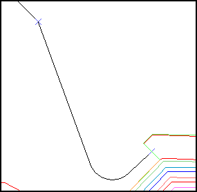
You should now see the curve as shown, created between the two tangents.
The design string number of 9 will be used for the road outline.
The road outline is created, as shown.
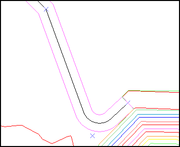
Note: The function MAKE PILLARS is used to create the
road outline in this example, as the function is a part of the Core
Module.
Note: To see all the steps performed in this section, run
1b_curve_tangent.tcl. You need to click
Apply on any forms presented.
Task: Design a road at a Constant Gradient Along Contours
In this task, you will create an access road with a maximum gradient of 5%. The road design will be based on a string file of topography contours.
- Click Reset graphics.
- Open pit&dump.str in Graphics.
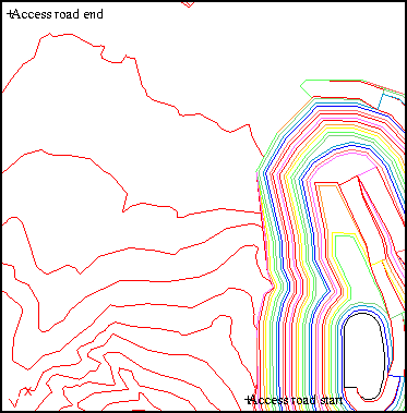
- Open access_start&end.str in Graphics.
- Choose Display > Point > Attributes.
- Enter the information as shown, and click Apply.
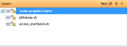
- In the Layers pane, double-click main graphics layer to set it as the default layer.
- Click the Design string button
on the Status bar.
- Enter the information as shown, and click Apply.
- Click the design grade button
 on the Status bar.
 - Enter the information as shown, and click Apply.
- Choose Create > Digitise > New point .
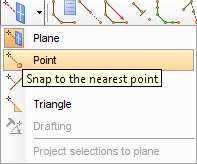
- Click the Snap mode drop-down, and select Point.
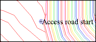
- Click the Access road start point as shown.
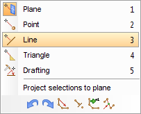
- Right-click in Graphics, and select Line.
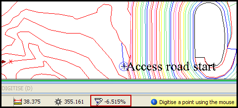
- Move the cursor along the contour as shown.
- Click on the contour line near Point 2 when the percentage value displayed in the Status bar is approximately -5%, as shown.
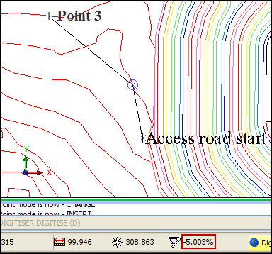
- Click on the contour line near Point 3, when the gradient is approximately -5%, as shown.
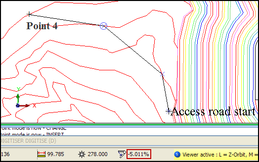
- Click on the next contour line near Point 4, when the gradient is approximately -5%, as shown.
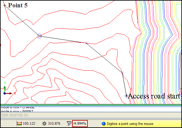
- Click on the next contour line near Point 5, when the gradient is approximately -5% as shown.
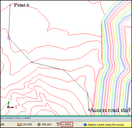
- Click on the next contour line near Point 6, when the gradient is approximately -5% as shown.
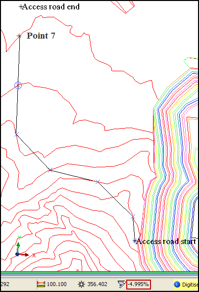
- Click on the next contour line near Point 7, when the gradient is approximately -5% as shown.
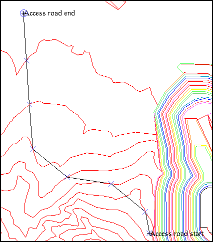
- Click the Access road end point, as shown.
-
Press ESC.
- Click the design string button
on the Status bar.
- Enter the information as shown, and click Apply.
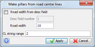
- Choose Design > Underground tools > Room & pillar from centrelines.
- Enter the information as shown, and click Apply.
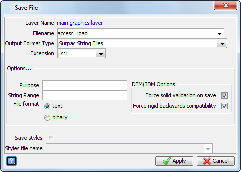
- Click Save
.
- Enter the information as shown, and click Apply.
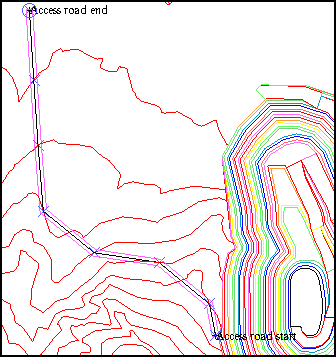
In this example, the goal is to create the shortest, straightest road possible between these two points, while ensuring that the maximum gradient is not more than 5%.
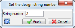
The design string number 2 will be used for the road centreline.
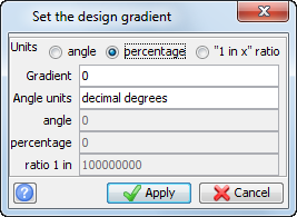
Note: In this example, you will not use the actual design
gradient value (set to zero in the previous form) to create
points. You will digitise points, and want to see the
gradient between any two points expressed as a percentage.
By setting the units to percentage, the
gradient between the digitised points will be displayed as a value in percent in the Status bar.
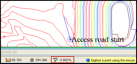
Note: As you move the cursor along the contour line, the gradient
(expressed as a percentage in the status bar) will change.
Remember that the goal is to create a road with a centreline
at a maximum gradient of 5%. Since we are designing from
the uppermost point down, the gradient will be -5%.
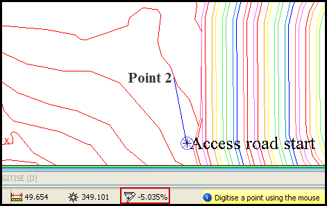
Note: There will be two or more locations along a contour where
the gradient will be the same. In this example, the points are selected based on the desire to create a road
that is as straight as possible.
The design string number of 9 will be used for the road outline.
The road outline is created, as shown.
Note: To see all the steps performed in this section, run
1c_access_road.tcl. You need to click
Apply on any forms presented.
Task: Create a variable width road outline
In this task, you will learn how to create a road outline of variable width from several centreline strings.
- Click Reset graphics.
- Open pit&dump.str in Graphics.
- Open all_centrelines.str in Graphics.
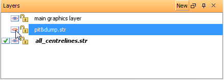
- In the Layers pane, click the eye icon to hide pit&dump.str.
- Choose Display > Strings > With string numbers.
- Enter the information as shown, and click Apply.
- Choose File tools > String maths.
- Enter the information as shown, and click Apply.
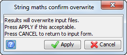
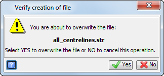
- If prompted, click Apply to overwrite the file.
- Open all_centrelines.str in Graphics.
Note: The output of the STR MATHS function is written to the file on
disk. To have the information available for MAKE
PILLARS, it must be re-opened in Graphics.
- Click the design string button
on the status bar.
- Enter the information as shown, and click Apply.
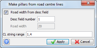
- Choose Design > Underground tools > Room & pillar from centrelines.
- Enter the information as shown, and then click Apply.
- Click Save .
- Enter the information as shown, and click Apply.
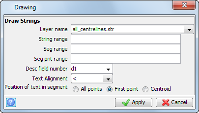
The road centreline strings are displayed.
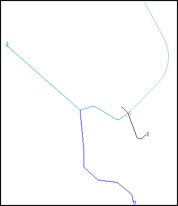

Note: The D1 field is set to the desired road width for each
string or string range.
The design string number 9 will be used for the road outline.
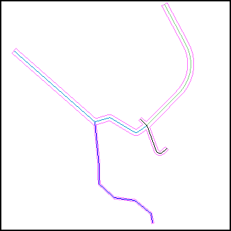
The road outline for all centrelines is created at the width specified in the D1 field.

Note: To see all the steps performed in this section, run
1d_variable_width_outline.tcl. You will need to click
Apply on any forms presented.