


Using the road design module
In this section, you will learn how to create a road design by using the Road Design Module. The workflow for this module is:
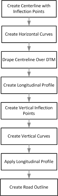
 Note: This workflow demonstrates the steps in this tutorial. There are other ways to achieve a result.
Task: View the data
- Click Reset graphics
 .
. - Open inflection_points.str in Graphics.
- Choose Display > Point > Numbers.
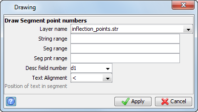
- Enter the information as shown, and click Apply.
- Open topo.dtm.
- Choose View > Surface view options > Lighting options, or click the
 icon.
icon. - Enter the information as shown, and click Apply.
- Choose Display > Surface or solid with colour banding.
- Enter the information as shown, and click Apply.
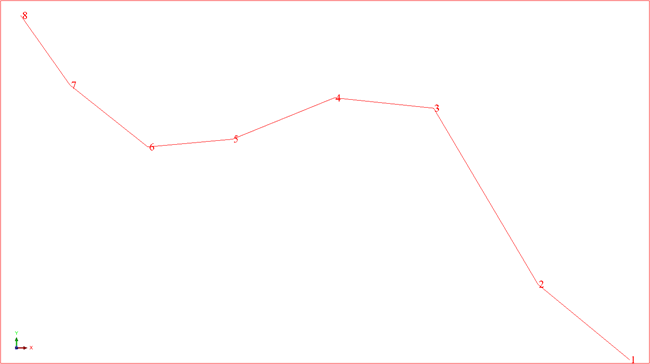
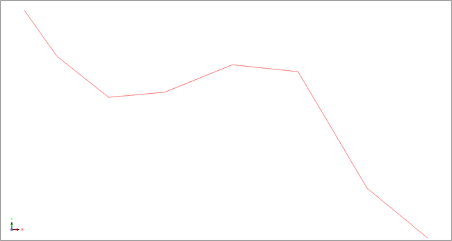
In this example, you will create a road design between points 1 and 8, with horizontal curves at each inflection point (2, 3, 4, 5, 6, and 7).
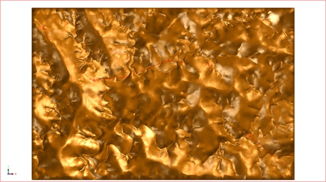
The DTM representing the surface topography is displayed.
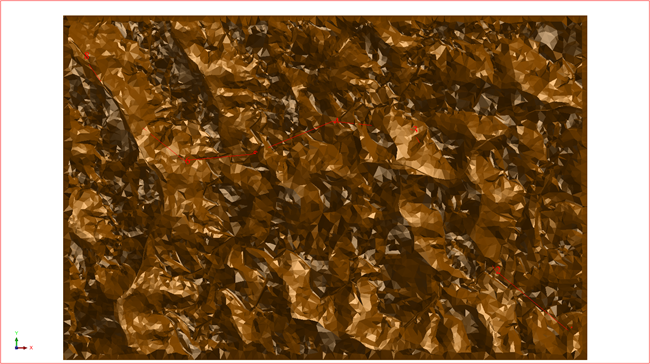
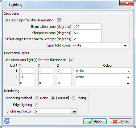
The Gourad rendering smooths the surface.
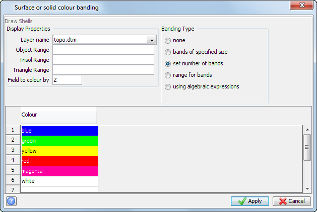
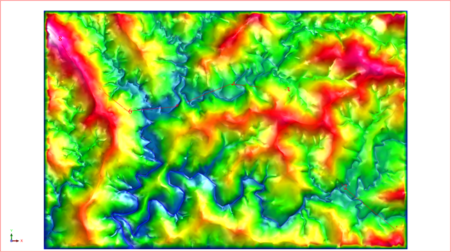
The lower elevations are coloured blue and green, and the higher elevations are magenta and white.
Note: To see all the steps performed in this section, run
2a_view_data.tcl. You will need to click Apply on any forms presented.
Task: Create horizontal curves
In this task, you will learn how to create horizontal curves from a string representing the start and end point of a road design, and one inflection point per horizontal curve. In this example, the inflection points, maximum vehicle velocity, and the radius for each curve are given. In practice, you would determine these values.
- Click Reset graphics.
- Open inflection_points.str in Graphics.
- Choose Road design > Design horizontal alignment.
- Click the string.
- Enter the information as shown, and click Calculate.
- After the transition and superelevation values have been
calculated, click Apply.
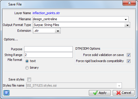
- Click Save
 .
. - Enter the information as shown, and click Apply.
In this example, you will design horizontal curves at each of the inflection points in this string.
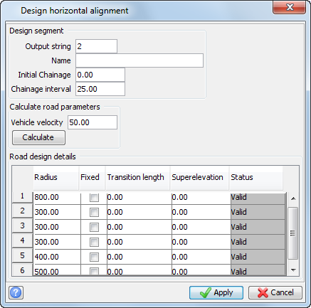
A new string is created in the current layer with the output string number of 2.
The name is optional and can be left blank. You can choose to enter a name if you want to create a map with this information.
"Chainage" values are the cumulative two-dimensional distances at each point along the design, and begin with the "Initial Chainage" value.
Points are created at the start and end of each simple and transition curve, and at the chainage interval of 25 meters along the curves.
The vehicle velocity is in kilometers per hour.
The radius of each curve is in meters.You must enter the radius for each curve to perform the calculation.
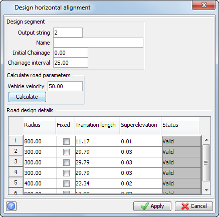
When you have clicked the Calculate button, transition lengths and superelevation values are calculated for each curve which is not nominated as "Fixed". In this example, all curves contain a transition curve.
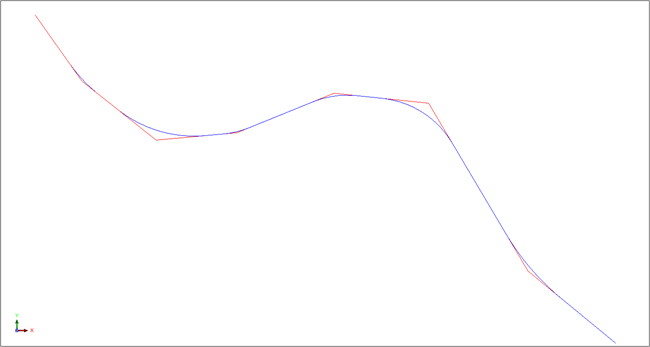
The horizontal curves are created in string 2, as displayed.
Note: To see all the steps performed in this section, run
2b_horizontal_design.tcl. You will need to click Apply on any forms presented.
Task: Drape centreline over DTM
- Click Reset graphics.
- Open topo.dtm in Graphics.
- Open design_centreline.str.
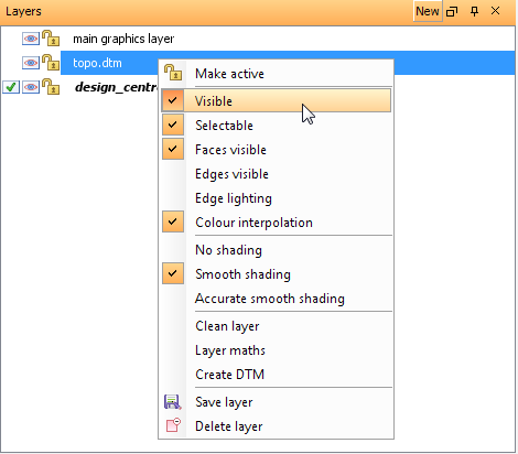
- In the Layers pane, right-click topo.dtm.
- Click Visible to hide the DTM.
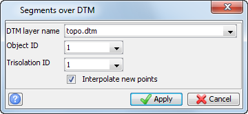
- Choose Road design > Drape segment over DTM.
- Click the string.
- Enter the information as shown, and click Apply.
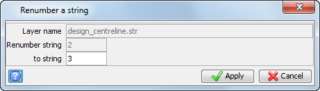
- Choose Edit > String > Renumber.
- Click the string.
- Enter the information as shown, and click Apply.
- Press ESC.
- In the Layers pane, right-click topo.dtm, and click Visible to display the DTM.
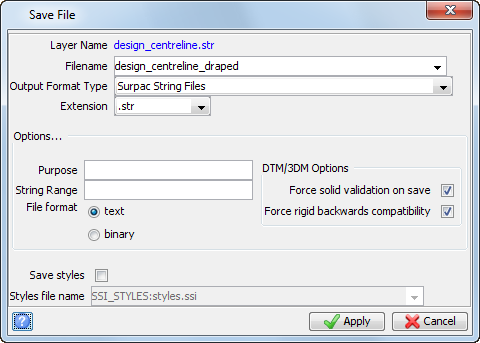
- Click Save .
- Enter the information as shown, and click Apply.
The string and DTM are displayed.
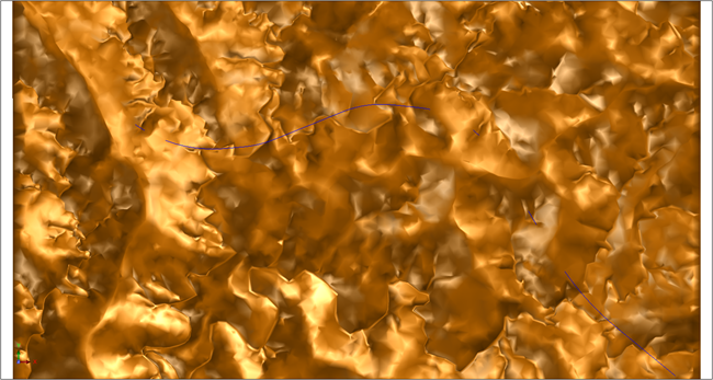
Note: You need to rotate the data in Graphics to view the string draped over the DTM.
Note: To see all the steps performed in this section, run
2c_design_centreline_draped.tcl. You need to click Apply on any forms presented.
Task: Create longitudinal profile
- Click Reset graphics.
- Open design_centreline_draped.str in Graphics.
- Choose Road design > Create longitudinal profile.
- Click the string.
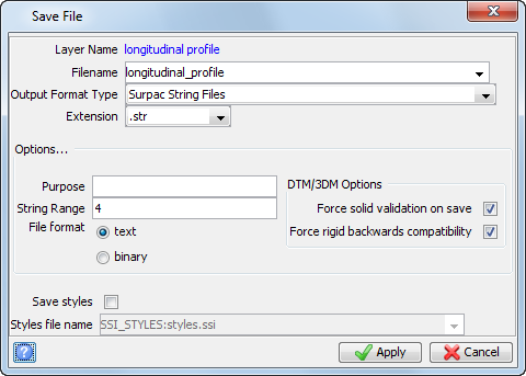
- Enter the information as shown, and click Apply.
- Click Save .
- Enter the information as shown, and click Apply.
The draped string is displayed.
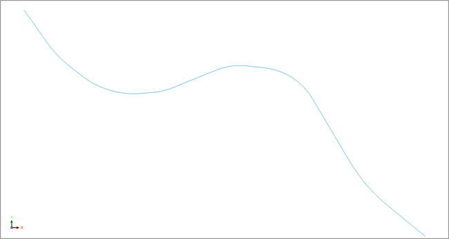
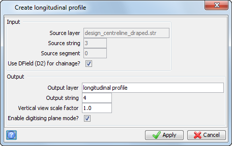
The longitudinal profile is displayed in the lower viewport.
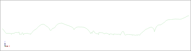
Note: You need to keep string 4 displayed in Graphics to perform the next task.
Note: To see all the steps performed in this section, run 2d_create_longitudinal_profile.tcl. You need to click Apply on any forms presented.
Task: Create vertical inflection points
Note: You need
the data displayed from the previous task. If you do not have the data displayed, run macro 2d_create_longitudinal_profile.tcl.
- Click the lower viewport.
- Click the Design string
 button in the Status bar.
 - Enter the information as shown, and click Apply.
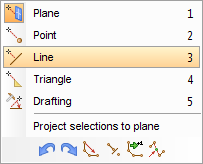
- Choose Create > Digitise > New point.
- Right-click in Graphics and choose Point, for the snap mode.
- Click the string at Point 1.
- Right-click in Graphics, and choose Plane.
- Click the string at Points 2 to 5.
- Right-click in Graphics, and choose Point.
- Click the string at Point 6.
- Press ESC.
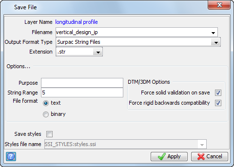
- Click Save .
- Enter the information as shown, and click Apply.
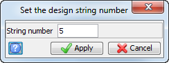
The numbered string is displayed.
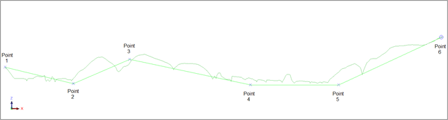
Note: You need to keep string 5 displayed in Graphics to perform the next task.
Note: To see all the steps performed in this section, run 2e_create_vertical_inflection_points.tcl. You need to click Apply on any forms presented.
Task: Create vertical curves
Note: You need the data displayed from the previous task. If you do not have the data displayed, run macro 2e_create_vertical_inflection_points.tcl.
- Click the lower viewport.
- Choose Road design > Design vertical alignment.
- Click string 5.
- Enter the information as shown, and click Apply.
- Click Save .
- Enter the information as shown, and click Apply.
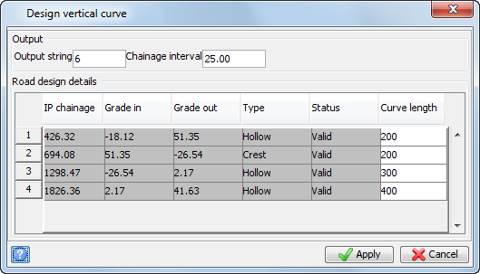
The vertical curves are displayed.
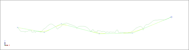
Note: You need to keep string 6 displayed in Graphics to perform the next task.

Note: To see all the steps performed in this section, run 2f_create_vertical_curves.tcl. You need to click Apply on any forms presented.
Task: Apply longitudinal profile
Note: You need the data displayed from the previous task. If you do not have the data displayed, run macro 2f_create_vertical_curves.tcl.
- Choose Road design > Apply longitudinal profile.
- Click the lower viewport.
- Press F1 to suspend the function.
- Zoom in on a curve.
- Press ESC to continue.
- Click string 6.
- Click in the upper viewport.
- Click string 3.
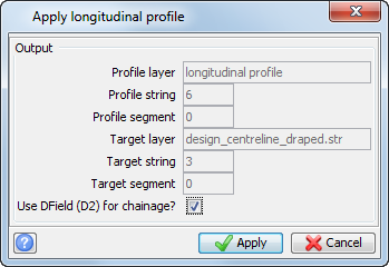
- Enter the information as shown, and click Apply.
- Choose Edit > Segment > Renumber.
- Click string 3.
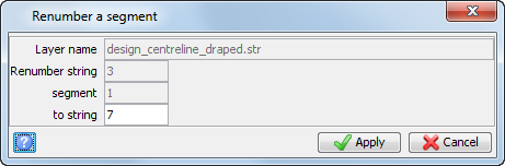
- Enter the information as shown, and click Apply.
- Click Save .
- Enter the information as shown, and click Apply.

Note: To see all the steps performed in this section, run
2g_apply_longitudinal_outline.tcl. You need to click Apply on any forms presented.
Task: Create road outline
- Click Reset graphics .
- Open final_centreline_design.str in Graphics.
- Choose Road design > Create road outline.
- Click the string.
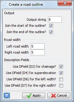
- Enter the information as shown, and click Apply.
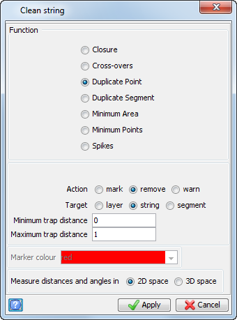
- Choose Edit > String > Clean.
- Enter the information as shown, and click Apply.
- Click the string.
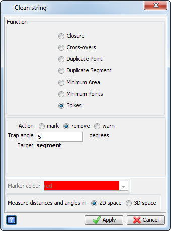
- Choose Edit > String > Clean.
- Enter the information as shown, and click Apply.
- Click the string.
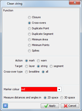
- Choose Edit > String > Clean.
- Enter the information as shown, and click Apply
- Click the string.
- Click Save .
- Enter the information as shown, and click Apply.
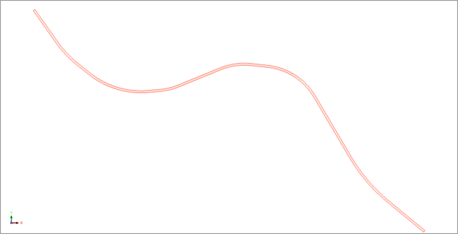
The road outline is displayed.

Note: To see all the steps performed in this section, run 2h_create_road_outline.tcl. You need to click Apply on any forms presented.