


Calculating road design volumes
Task: Calculate road cut
- Click Reset graphics
 .
. - Open final_road_outline.str in Graphics.
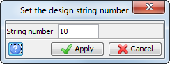
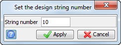
- Click the Design string
 button on the Status bar.
 - Enter the information as shown, and click Apply.
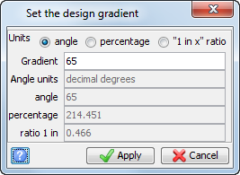
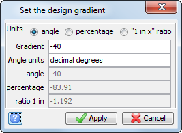
- Choose Pit design > Set slope gradient.
- Enter the information as shown, and click Apply.
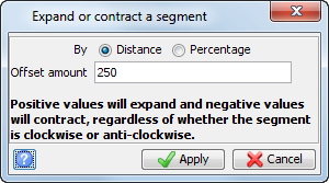
- Choose Edit > Segment > Expand/Contract.
- Click the road outline in Graphics.
- Enter the information as shown, and click Apply.
- Press ESC.
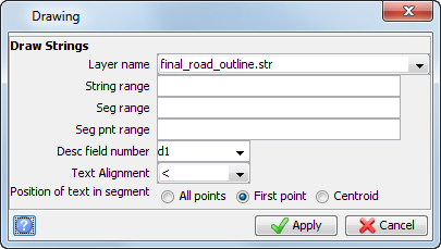
- Choose Display > Strings > With string numbers.
- Enter the information as shown, and click Apply
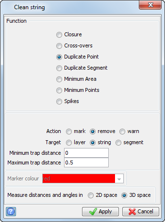
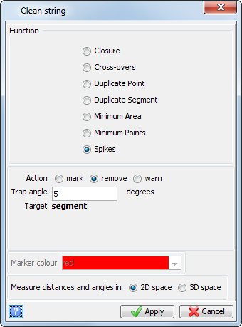
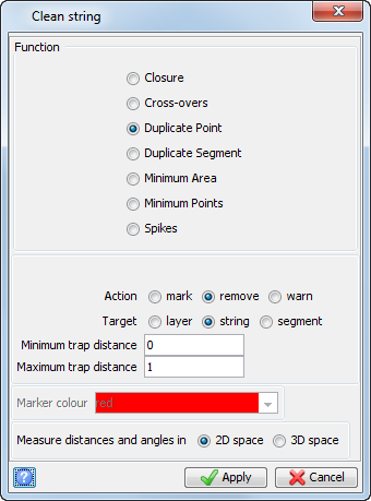
- Choose Edit > String > Clean.
- Enter the information as shown, and click Apply.
- Click string 10.
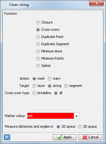
- Choose Edit > String > Clean.
- Enter the information as shown, and click Apply.
- Click string 10.
- Choose Edit > String > Clean.
- Enter the information as shown, and click Apply.
- Click string 10.
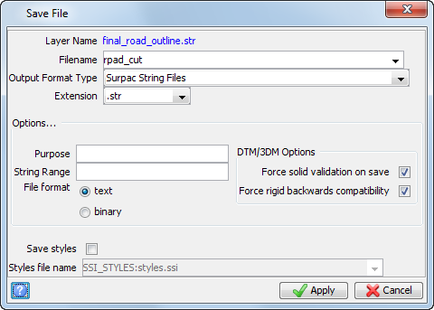
- Click Save
 .
. - Enter the information as shown, and click Apply.
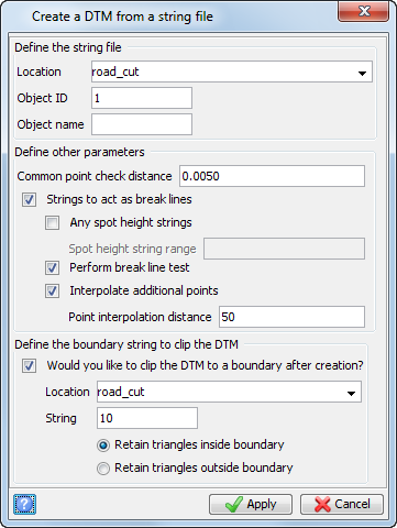
- Choose Surfaces > DTM File functions > Create DTM from string file.
- Enter the information as shown, and click Apply.
- Click Reset graphics .
- Open road_cut.dtm in Graphics.
- Open topo.dtm in Graphics.
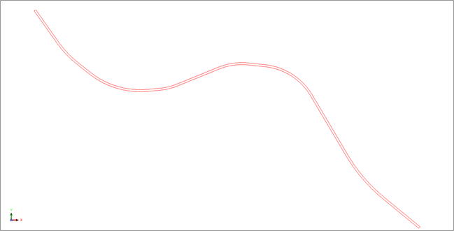
The road outline string is displayed.
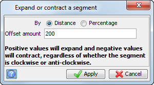
The expanded string is displayed.
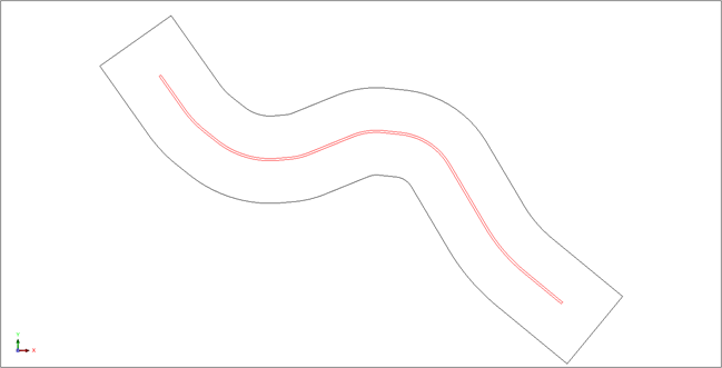
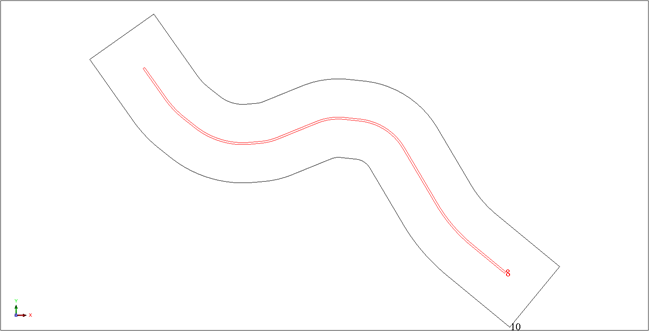
The road outline with string 8 and string 10 displayed.
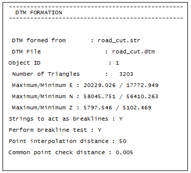
The road cut log report is displayed.
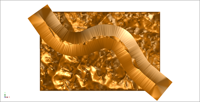
The DTM is displayed.
 Note: To see all the steps performed in this section, run
3a_road_cut_dtm.tcl. You need to click
Apply on any forms presented.
Note: To see all the steps performed in this section, run
3a_road_cut_dtm.tcl. You need to click
Apply on any forms presented.
Task: Calculate road cut volume
- Click Reset graphics .
- Open road_cut.dtm in Graphics.
- Open topo.dtm in Graphics.
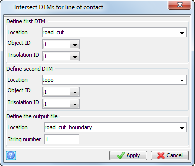
- Choose Surfaces > DTM File functions > Line of intersection between 2 DTMs.
- Enter the information as shown, and click Apply.
- If prompted, click Yes to overwrite the file.
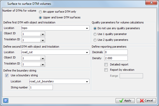
- Choose Surfaces > Volumes > Net volume between DTMs.
- Enter the information as shown, and click Apply.
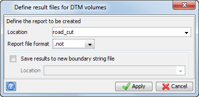
- Enter the information as shown, and click Apply.
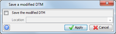
- Enter the information as shown, and click Apply
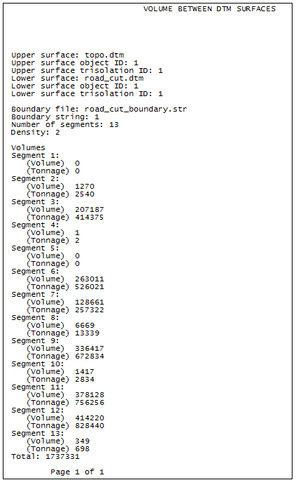
The road cut volume report is displayed.
Note: To see all the steps performed in this section, run
3b_road_cut_volume.tcl. You need to click Apply on any forms presented.
Task: Calculate road fill
- Click Reset graphics .
- Open final_road_outline.str in Graphics.
- Click the Design string button on the Status bar.
- Enter the information as shown, and click Apply.
- Click the Design slope
 button on the Status bar.
 - Enter the information as shown, and click Apply.
- Choose Edit > Segment > Expand/Contract.
- Click the string.
- Enter the information as shown, and click Apply.
- Click ESC.
- Choose Display > Strings > With string numbers.
- Enter the information as shown, and click Apply.
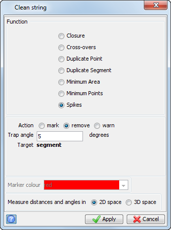
- Choose Edit > String > Clean.
- Enter the information as shown, and click Apply.
- Click string 10.
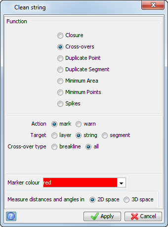
- Choose Edit > String > Clean.
- Enter the information as shown, and click Apply.
- Click string 10.
- Choose Edit > String > Clean.
- Enter the information as shown, and click Apply.
- Click string 10.
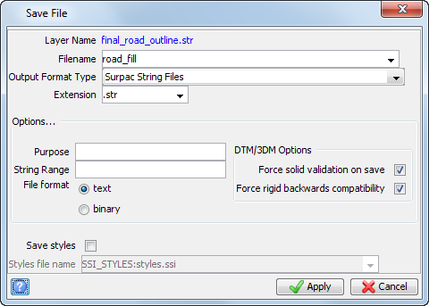
- Click Save .
- Enter the information as shown, and click Apply.
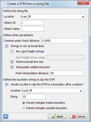
- Choose Surfaces > DTM File functions > Create DTM from string file.
- Enter the information as shown, and click Apply.
The expanded string is displayed.
The road outline with string 8 and string 10 displayed.
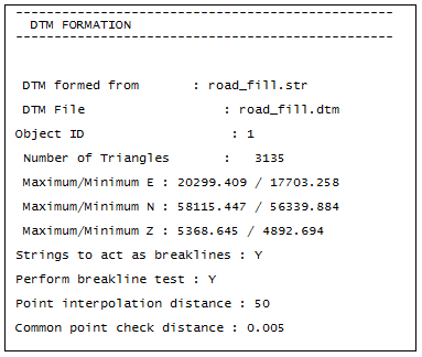
The road fill log report is displayed.
Note: To see all the steps performed in this section, run
3c_road_fill_dtm.tcl. You need to click
Apply on any forms presented.
Task: Calculate road fill volume
- Click Reset graphics .
- Open road_fill.dtm in Graphics.
- Open topo4fill.dtm in Graphics.
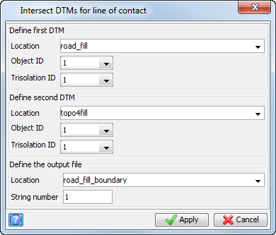
- Choose Surfaces > DTM File functions > Line of intersection between 2 DTMs.
- Enter the information as shown, and click Apply.
- Choose View > Surface view options > Hide triangle faces to hide the face attributes.
- Drag road_fill_boundary.str into Graphics.
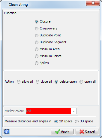
- Choose Edit > String > Clean.
- Enter the information as shown, and click Apply.
- Click the string.
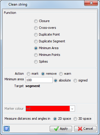
- Choose Edit > String > Clean.
- Enter the information as shown, and click Apply.
- Click the string.
- Choose Edit > String > Clean.
- Enter the information as shown, and click Apply.
- Click the string.
- Choose View > Surface view options > Hide triangle faces to display the face attributes.
- Click Save .
- Enter the information as shown, and click Apply.
- Choose Surfaces > Volumes > Net volume between DTMs.
- Enter the information as shown, and click Apply.
- Enter the information as shown, and click Apply.
- Enter the information as shown, and then click Apply.
The DTM is displayed.
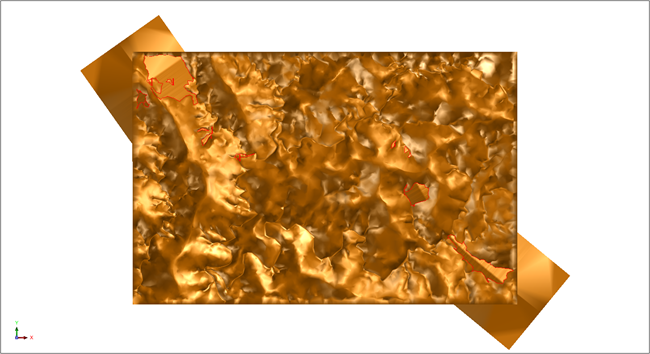

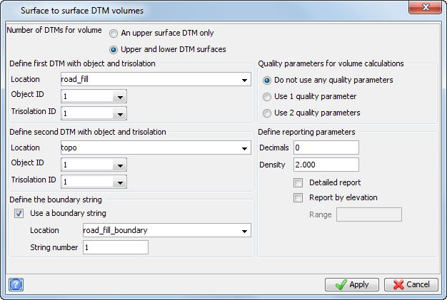
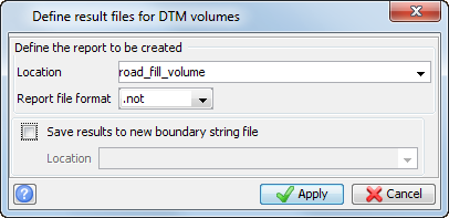
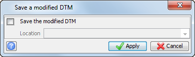
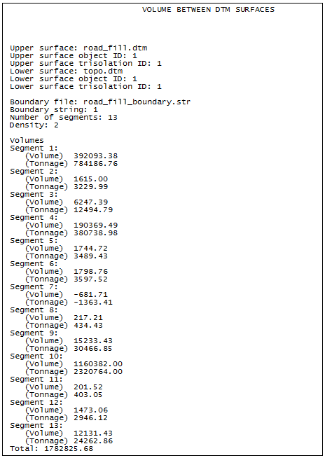
The road fill volume report is displayed.
Note: To see all the steps performed in this section, run
3d_road_fill_volume.tcl. You need to click Apply on any forms presented.