Task: Sending a grid and title block to DraftSight in separate layers
When you create a .dwf in Surpac, and then open it in DraftSight, the data is contained in a single layer. You can use the steps in the following task to create the grid and title block in separate layers from the geological or physical features you want to show.
This task uses the technique of creating a 'reference drawing'. A reference drawing is a drawing you can reuse in multiple plots.
- Open pit1.str in Graphics.
- Click Autoplot.
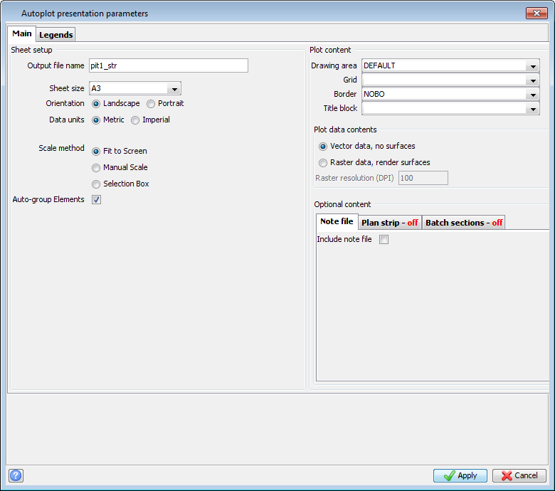
- Fill in the Autoplot presentation parameters form as shown, and click Apply.
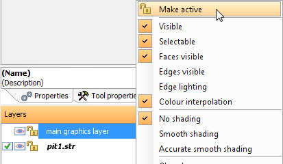
- In Surpac, in the Layer Manager, right-click on main graphics layer, and choose Make active.
- In the Surpac Layer Manager, right-click on pit1.str and choose Delete Layer.
- Click Autoplot.
- Fill in the form as shown, and then click Apply.
- Fill in the Grid Line Spacing and grid style form as shown, and click Apply.
- In DraftSight, click the Model tab.
- Click a line of the grid to select the grid.
- Choose File > Export > Export Drawing.
- Fill in the Save File form as shown, and click OK.
- Choose Window > pit1_str.dwf.
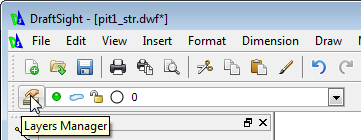
- Click Layers Manager.
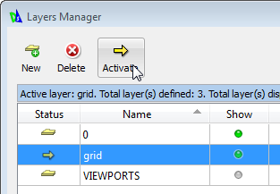
- Click New, type
grid, and click Activate. - Click OK.
- Select the Model tab.
- Choose Insert > Reference Drawing.
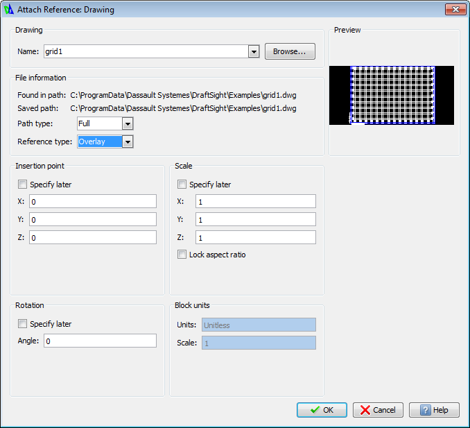
- Browse to the reference drawing you created, for example c:\ProgramData\Dassault Systems\DraftSight\Examples\grid1.dwg, select it, and click Open.
- Fill in the Attach Reference Drawing form as shown, and click OK.
- Select the Layout1 tab to change the background colour to white again..
- Click Save, and save the file.
- Click Layers Manager.
- In the Layers Manager, select the 0 layer.
- In the Layers Manager, click New, type
titleBlock, click Activate, and click OK. - In Surpac, click Autoplot.
- Fill in the Autoplot presentation parameters form as shown, and click Apply.
- Type a title in the User definable title block lines form, and click Apply.
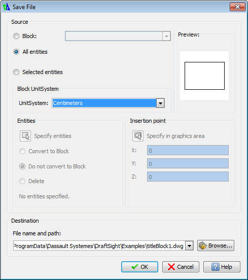
- In DraftSight, choose File > Export > Export Drawing.
- Fill in the Save File form as shown, and click OK.
- Select Window > pit1_str.dwg.
- Select the Model tab.
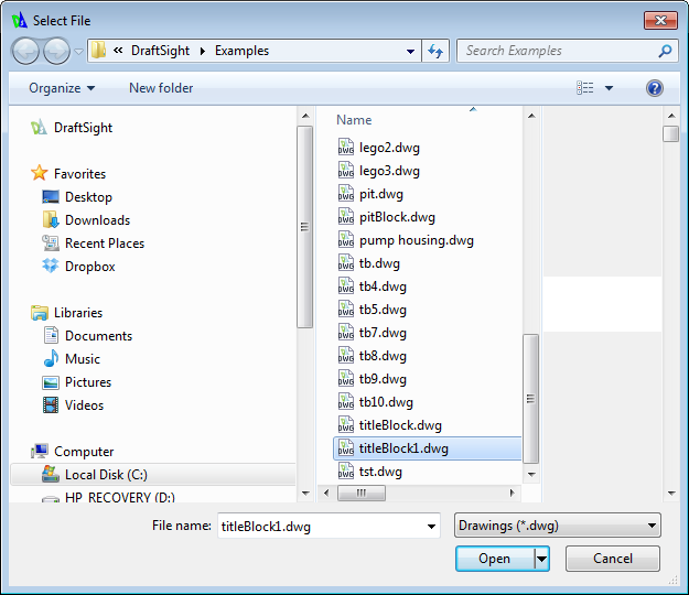
- Choose Insert > Reference Drawing.
- Select the titleBlock1.dwg reference drawing, and click Open.
- In the Attach Reference Drawing form, click OK.
- Click the Layout1 tab.
- Click Layers Manager.
- In the Layers Manager, click the green Show radio button for the grid layer to turn the Show setting off, and click OK in the Layers Manager.
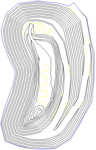
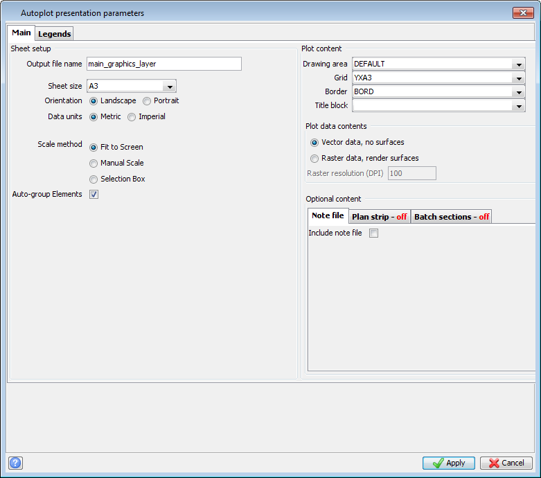
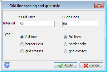
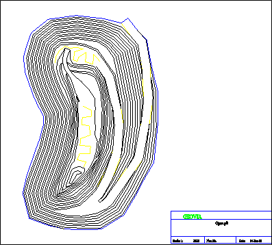
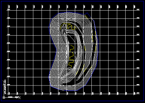
The grid and border are displayed in DraftSight in a new .dwf file.
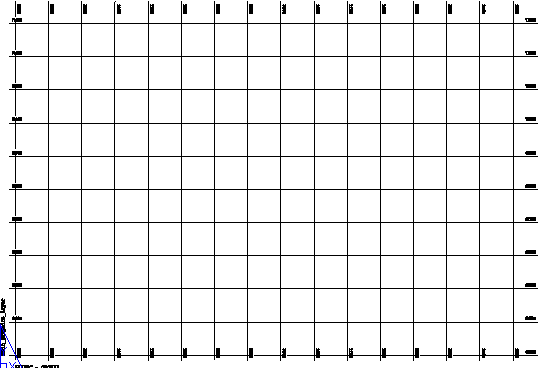
 Note: The Model tab presents a slightly different view of the data you have displayed (in this example, the grid). On the Model tab you can select the grid.
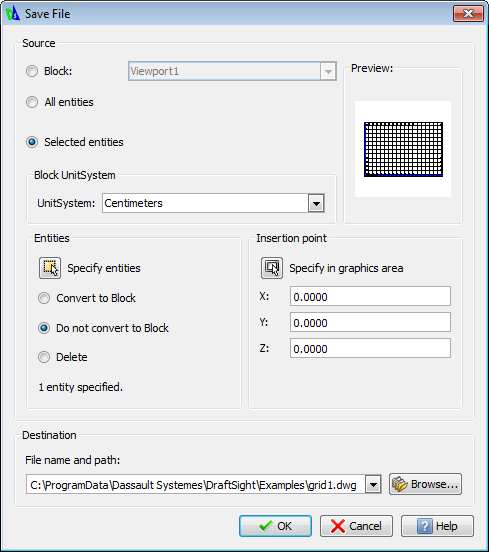
 Tip: It is important to remember the File name and path that you entered so you know where to find the reference drawing that you have just created.
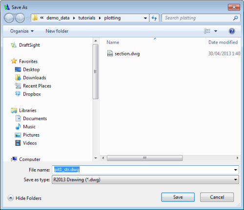
The file is saved in .dwg format.
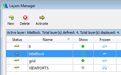
Note: You cannot activate a layer that is 'frozen'. The VIEWPORTS layer is frozen so if you want to create a new layer, create it above the VIEWPORTS layer.
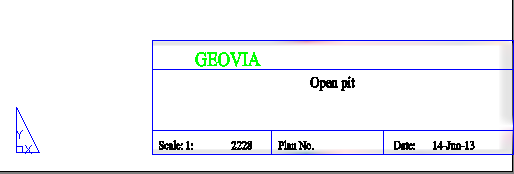
Next you will create a reference drawing of the title block. This allows you to have the title block in a separate layer from the grid and the pit. Conversely, if you did not need to show or hide the three elements independently, you would autoplot the three elements in a single operation.
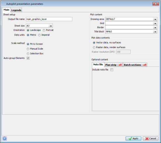
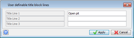
The title block is displayed in DraftSight.
The pit and the grid are displayed, and the titleBlock layer is active.
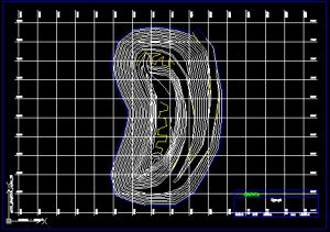
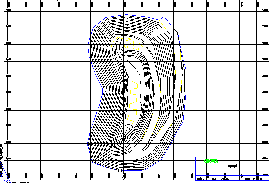
The grid is hidden but the pit and the title block remain displayed.