


Data preparation
Create ore outlines
Geological outlines are a good source of information when performing pit design. They can be obtained from slicing a geological model (solid or wireframe) or taken from bench by bench interpretations.
Task: Create the ore outlines
- Connect to pitdesign.mdl.
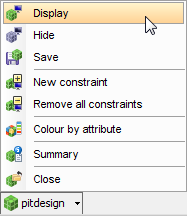
- Click the pitdesign icon on the Status bar, and choose Display.
- Enter the information as shown, and click Apply.
- Choose Block model > Constraints > New graphical constraint.
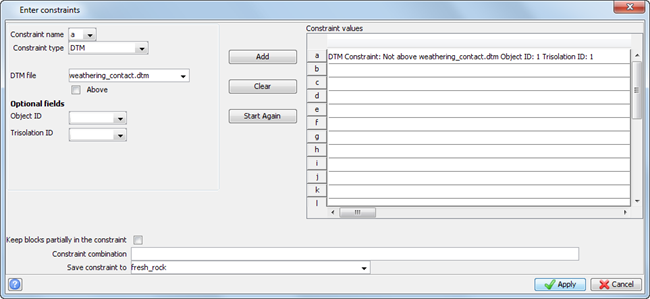
- Enter the information as shown, click Add, and click Apply.
- Choose Block model > Display > Colour model by attribute.
- In the Attribute to colour by, select gold and click Scan.
- In the Ranges for colour selection, type "0,8,1;999" and click Refresh.
- Click Apply.
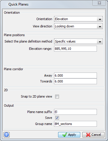
- Choose Planes > Quick planes.
- Enter the information as shown, and click Apply.
- Press F12 to move to the next plane.
- Continue press F12 until you have viewed each plane.
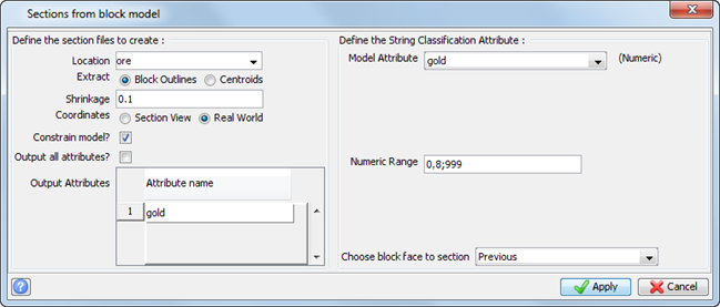
- Choose Block model > Sections > Create.
- Enter the information as shown, and click Apply.
- Enter the information as shown, and click Apply.
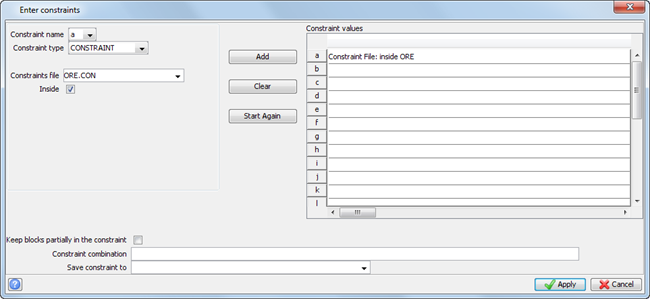
- Enter the information as shown, click Add, and click Apply.
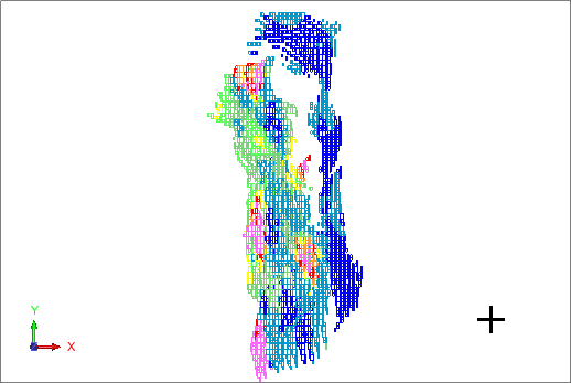
- The sections are written to new string files.
- Click Reset graphics
 .
. - Hold CTRL and select all of the new section string files in the Navigator.
- Continue to hold CTRL and drag the files into Graphics.
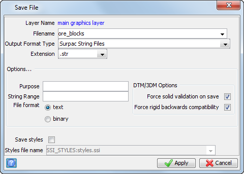
- Choose File > Save > string/DTM.
- Enter the information as shown, and click Apply.
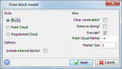
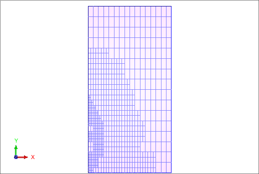
The block model is displayed.
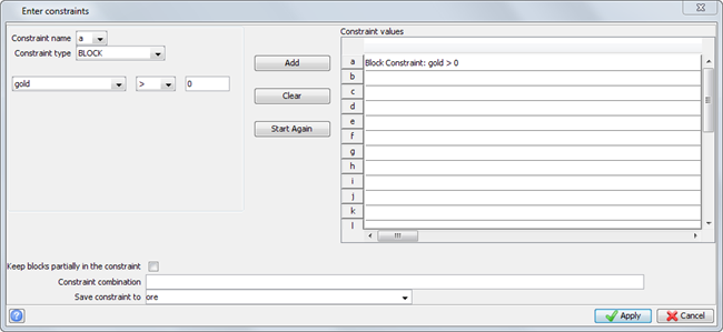
The constrained block model is displayed.
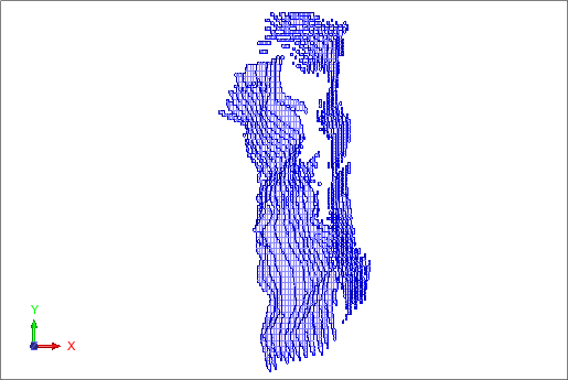
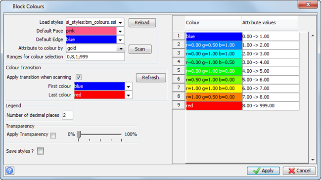
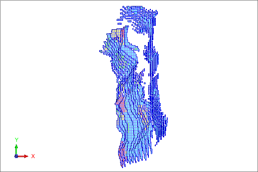
The block model is coloured by gold grade.
 Note: The planes you have created are temporary, and the data in each of the sections you have viewed in Graphics is not saved in individual files. To save the data in the active plane to a string file, you can choose Planes > Save section to string files. To save all planes in a group, you would need to perform this function for each plane created. The following steps use the section function in the block model module to create and save the sections in a single function.
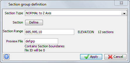
That is, select ore885.str, ore895.str, ore905.str, ore915.str, ore925.str, ore935.str, ore945.str, ore955.str, ore965.str, ore975.str, ore985.str, and ore995.str.
The sections open in the same layer.
Note: To see all of the steps performed in this task, run _02_create_ore_outlines.tcl. You need to click Apply on any forms presented.
Viewing Whittle outlines
Task: View Whittle outlines from the Surpac block model
- Click Reset graphics .
- Connect to pitdesign.mdl.
- Click the pitdesign icon on the Status bar, and choose Display.
- Enter the information as shown, and click Apply.
- Choose Block model > Constraints > New graphical constraint.
- Enter the information as shown, and click Apply.
- Rotate the model in Graphics to view the data.
- Choose Block model > Constraints > Remove all graphical constraints.
-
Choose Block model > Constraints > New graphical constraint.
- Enter the information as shown, and click Apply.
- Choose Block model > Display > Colour model by attribute.
- Enter the information as shown, click Scan, and click Apply.
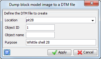
- Choose Block Model > Block model > Export > Block faces to DTM.
- Enter the information as shown, and click Apply.
- Click the pitdesign icon on the Status bar, and choose Close.
- Open pit28.dtm in Graphics, and rotate to view the pit.
- Click Section view
 .
. - Choose Display > 2D grid.
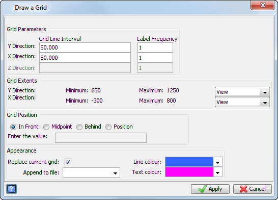
- Enter the information as shown, and click Apply.
- Choose Solids > Solids tools > Create sections.
- Enter the information as shown, and click Apply.
- Enter the parameters as shown, and click Apply.
- Click Reset graphics .
- Hold CTRL and select all of the section files you have just created in the Navigator.
- Continue to hold CTRL drag the files into Graphics.
- The sections strings open in one layer.
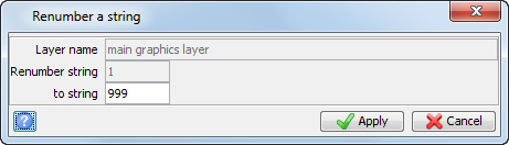
- Choose Edit > String > Renumber, and click a string in Graphics.
- Enter the information as shown, and click Apply.
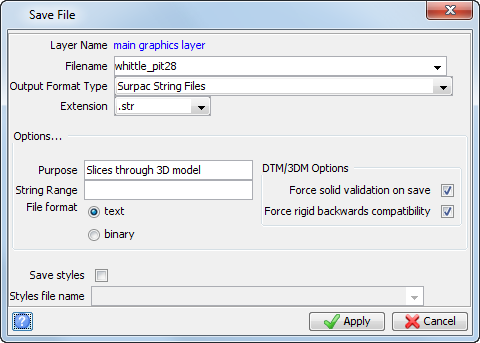
- Choose File > Save > string/DTM.
- Enter the information as shown, and click Apply.
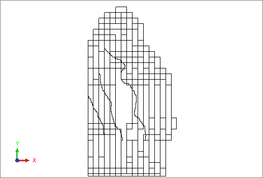
The block model is displayed.
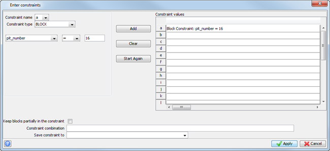
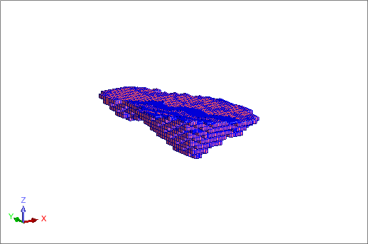
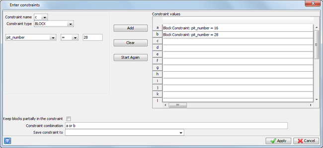
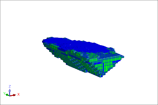
The Whittle pit shells 16 and 28 are displayed.
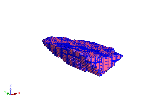
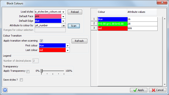
The two Whittle pit shells, 16 and 28, are displayed in different colours.
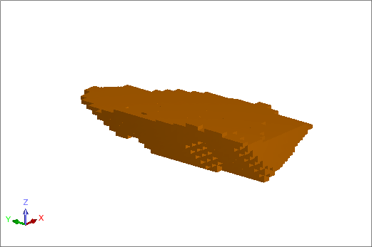
The data is displayed in section view.
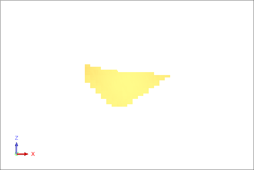
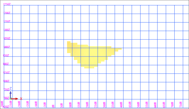
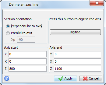
This will give a vertical axis for slicing the DTM.
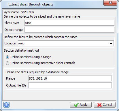
There are two results produced by the Slice Object function. The first result is a range of string files called wmb805 to wmb1085 in increments of 10, which contain the extracted horizontal sections. These files are saved to disk. The second result is a layer called slice which contains the extracted sections. If required, you can activate this layer and save all the sections to a single file.
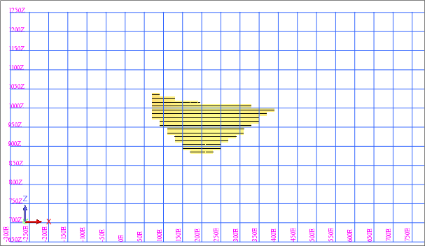
That is, select wmb885.str, wmb895.str, wmb905.str, wmb915.str, wmb925.str, wmb935.str, wmb945.str, wmb955.str, wmb965.str, wmb975.str, wmb985.str, wmb995.str, wmb1005.str, wmb1015.str, wmb1025.str, and wmb1035.str.
Note: To see all of the steps performed in this task, run _03_create_whittle_outlines.tcl. You need to click Apply on any forms presented.
Add slope values
Task: Add slope values to the block model
- Click Reset graphics .
- Connect to pitdesign.mdl.
- Click the pitdesign icon on the Status bar, and choose Display.
- Enter the information as shown, and click Apply.
- Open slo1.str in Graphics.
- The block model and slope string file are displayed.
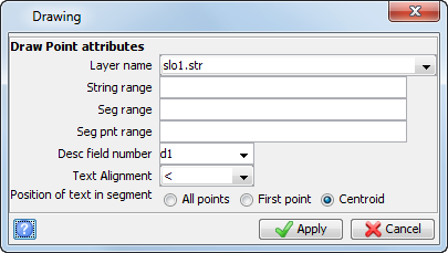
- Choose Display > Point > Attributes.
- Enter the information as shown, and click Apply.
- Open weathering contact.dtm in Graphics.
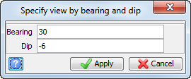
- Choose View > Data view options > View by bearing & dip.
- Enter the information as shown, and click Apply.
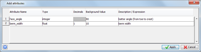
- Choose Block model > Attributes > New.
- Enter the information as shown, and click Apply.
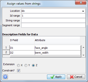
- Choose Block model > Estimation > Assign value from polygon.
- Enter the information as shown, and click Apply.
- Enter the information as shown, and click Apply.
- Choose Block model > Display > Colour model by attribute.
- Enter the information as shown, click Scan, and click Apply.
- Choose File > Save > Block model.
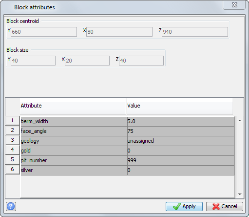
- Choose Block model > Display > View attributes for one block.
- Click a block in Graphics.
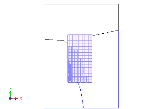
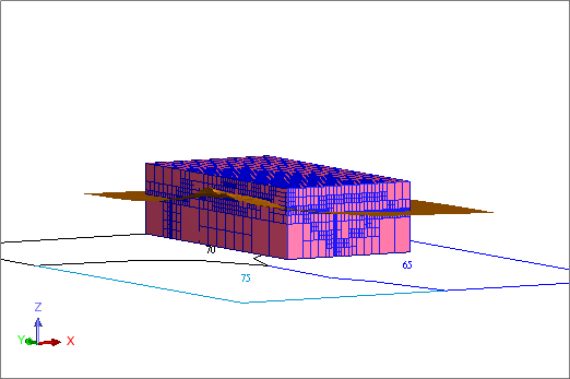
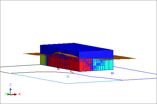
The block model, slope string, and DTM surface are displayed.
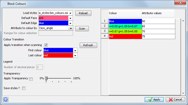
The block model is coloured by face angle.
The Block attributes form displays information similar to the following.
Note: To see all of the steps performed in this task, run _04_add_slope_values_to_blockmodel.tcl. You need to click Apply on any forms presented.
Load the outline and Whittle model
Task: Load the outline and Whittle model
- Click Reset graphics .
- Open ore_blocks.str in Graphics.
- Open whittle_pit28.str in Graphics.
- Connect to pitdesign.mdl.
- Click Zoom all
 .
.
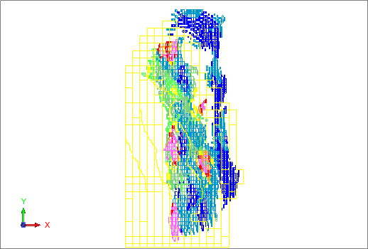
The ore outlines, pit, and model are displayed.
Note: To see all of the steps performed in this task, run _05_load_outline_and_whittle_model.tcl. You need to click Apply on any forms presented.