


Basic pit design tools
Task: Define the starting string
In this task you will be designing from the bottom of the pit up so you will use a digitised string based on information from the Whittle model. Remember, when designing the base of the pit, you must take into account the minimum pit width.
 Note: Before you attempt the steps in this procedure you must complete the previous task, Load the outline and Whittle model, or run macro _05_load_outlines_and_model.tcl.
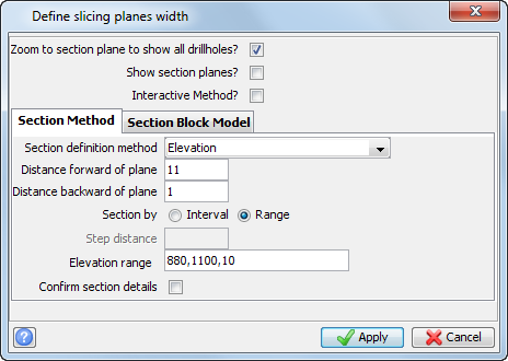
- Choose View > Viewing planes > Create graphical sections.
- Enter the information as shown, and click Apply.
- Open bas880.str in Graphics.
- Choose View > Zoom > Out.
- In the Function Chooser, type HOF, and press ENTER.
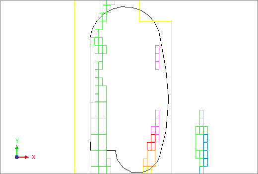
The base is at an elevation of 880 and the blocks are between 880 and 890. For this reason, if you leave Hide On you would not be able to see the base where it passes below the blocks. With Hide Off, you should be able to see the whole outline, as shown.
Note: To see all of the steps performed in this
section, run _06_load_base_string.tcl. You need to click Apply on any forms presented.
Task: Define the slope method
Note: Before you attempt the steps in this procedure you must have completed the previous tasks, Load the outline and Whittle model and Define the start string, or run macro _06_load_base_string.tcl.
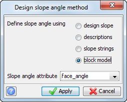
- Choose Pit design > Select slope method.
- Enter the information as shown, and click Apply.
Note: To see all of the steps performed in this task, run _07_define_slope_berm_width.tcl. You need to click Apply on any forms presented.
Task: Define a new ramp
Note: Before you attempt the steps in this procedure you must have completed the previous tasks, Load the outline and Whittle model, Define the start string, and Define the slope method. Alternatively, you can run macro _07_define_slope_berm_width.tcl.
- If bas880.str is not the active layer, right-click it in the Layers pane, and choose Make active.
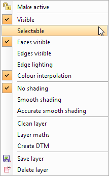
- In the Layers pane, right-click on ore_blocks.str and whitle_pit28.str, and clear Selectable, to stop these layers being selected in Graphics.
- In the Planes panel, double-click plane 885El in the BM_sections group.
- Choose Pit design > New ramp.
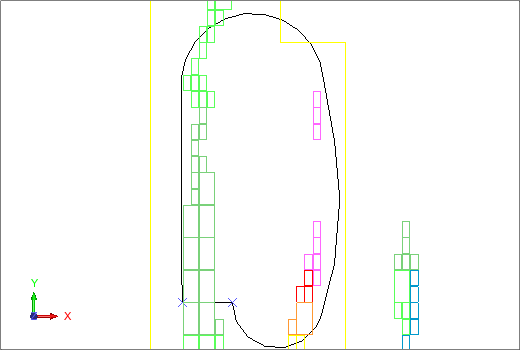
- Select the ramp points as shown.
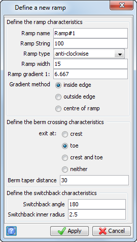
- Enter the information as shown, and click Apply.
Note: To see all of the steps performed in this task, run _08_define_new_ramp.tcl. You need to click Apply on any forms presented.
Task: Expand by bench height and berm width
Note: Before you attempt the steps in this procedure you must have completed the previous tasks, Load the outline and Whittle model, Define the start string, Define the slope method, and Define a new ramp. Alternatively, you can run macro _08_define_new_ramp.tcl.
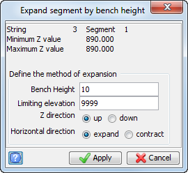
- Choose Expand segment > By bench height.
- Click on the string in Graphics.
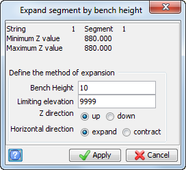
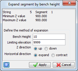
- Enter the information as shown, and click Apply.
- The segment is expanded.
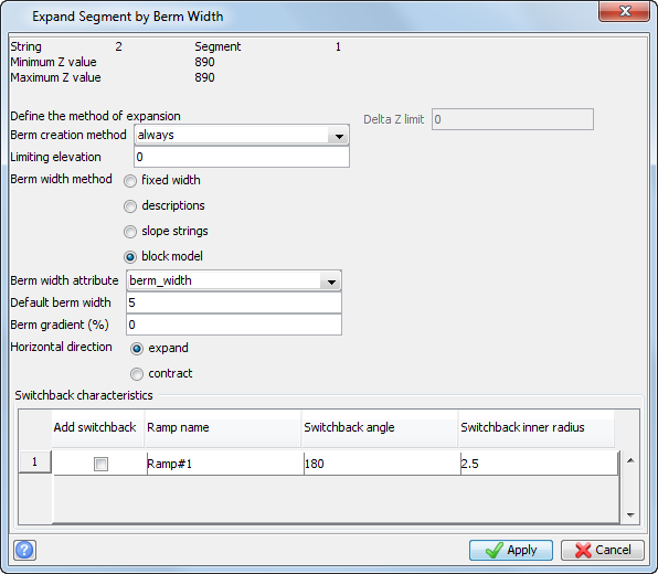
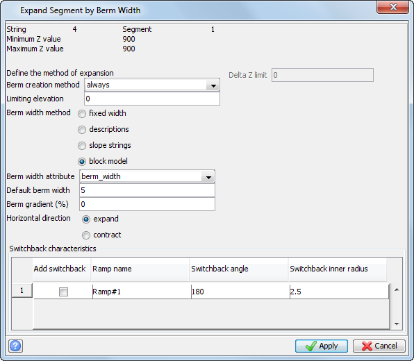
- Choose Expand segment > By berm width, and click on the ramp.
- Enter the information as shown, and click Apply.
- The segment is expanded.
- In the Planes panel, click Next plane
 .
. - Choose Expand segment > By bench height.
- Click on the last part of the pit that was created.
- Enter the information as shown, and click Apply.
- Choose Expand segment > By berm width.
- Click on the last part of the pit that was created.
- Enter the information as shown, and click Apply.
- Press ESC.
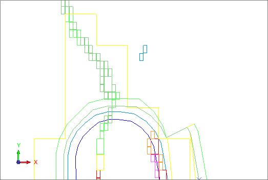
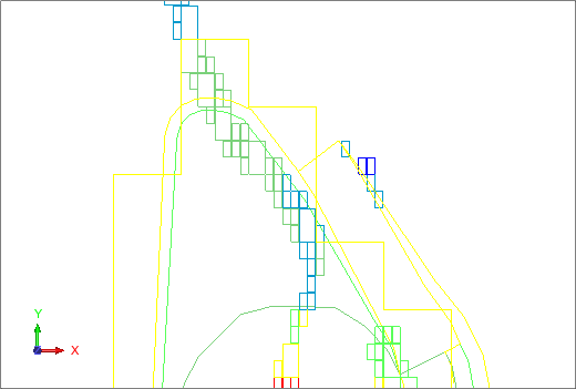
- Zoom in on the top of the design as shown.
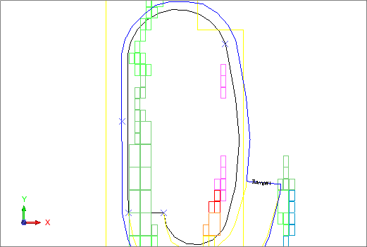
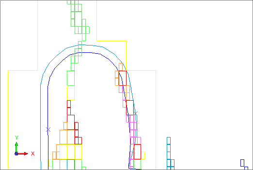
The segment is expanded.
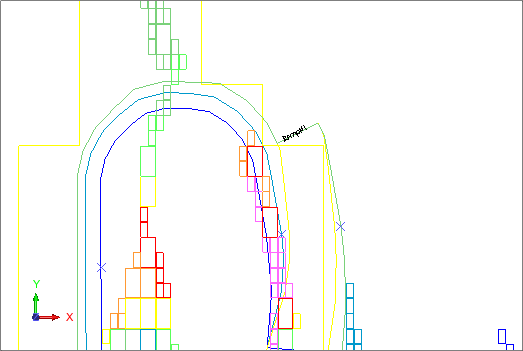
The segment is expanded.
Note: To see all of the steps performed in this task, run _09_expand_bench_height_berm_width.tcl. You need to click Apply on any forms presented.
Task: Edit a pit design
Note: Before you attempt the steps in this procedure you must have completed the previous tasks, Load the outline and Whittle model, Define the start string, Define the slope method, Define a new ramp, and Expand by bench height and berm width. Alternatively, you can run macro _09_expand_bench_height_berm_width.tcl.
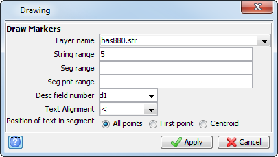
- Choose Display > Point > Markers.
- Enter the information as shown, and click Apply.
- Choose Edit > Point > Move.
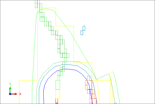
- Move the points to encompass the ore as shown.
- In the Planes panel, click Next plane .
- Choose Expand segment > By bench height.
- Click the line for which you moved the points.
- Enter the information as shown, and click Apply.
- The section is expanded.
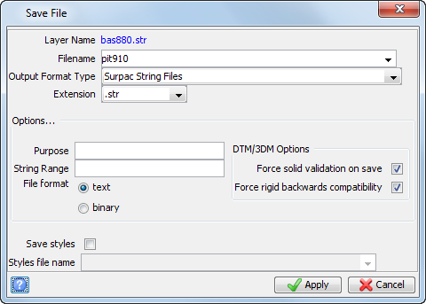
- Choose File > Save > string/DTM.
- Enter the information as shown, and click Apply.
- Open pit910.str in Graphics.
- In the Layers panel, right-click on bas880.str and choose Delete layer.
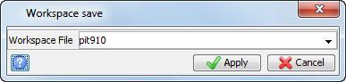
- Choose File > Save > Graphics workspace.
- Enter the information as shown, and click Apply.
- Click Reset graphics
 .
. - Click the pitdesign icon on the Status bar, and choose Close.
Note: To see all of the steps performed in this task, run _10_edit_design.tcl. You need to click Apply on any forms presented.