


Planes
Planes definitions are "corridors" in space used for displaying data. The definitions are created by defining a flat plane (horizontal, vertical, or inclined) with a "towards" and "away" distance. The corridor width is equal to the towards distance plus the away distance. Planes definitions are simply referred to as planes. When a plane is active, data within the corridor is displayed, and data outside the corridor is hidden.
Viewing planes can be useful for a number of tasks. Geologists use planes to view vertical cross-sections of drillhole and surface topography data. Engineers use planes to view horizontal sections of a block model while creating a pit design. Surveyors use planes to create cross-sections of areas which have been mined to display the cut for a specified period.
Active plane
The "active plane" is the plane on which the data is projected in Graphics. By default, if you have not selected a plane, the initial plane that is active when you start Surpac is a horizontal plane that has an elevation of zero with projection distances of 10000 above and below. Any data beyond the projection distances from this plane (that is, outside the corridor) is hidden.
You can find out which plane is active in Graphics by looking at the Status bar or the Planes panel. The Status bar shows you the name of the active plane.

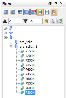
The Planes panel shows a check mark next to the active plane.
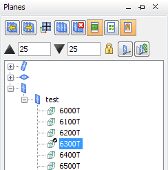
Planes panel
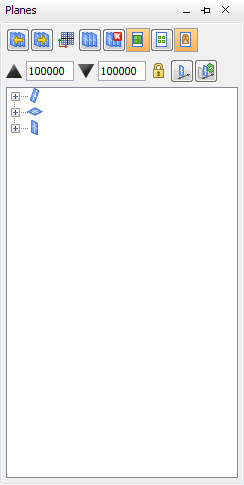
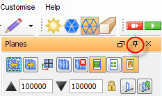
The Planes panel is available on start-up at the upper right of Graphics. By default, the panel is collapsed. You can view the panel by clicking it, and you can unpin the panel to change its location.
Storing planes
You can create, view, and interact with a group of planes and store them temporarily or permanently to planes files in the Plan view, Vertical sections, or Incline sections folders. If you store planes temporarily, when you exit Surpac, the planes are removed from the planes folders. However, if you store planes permanently, the planes will be available for future sessions in Surpac.
Planes viewing modes
You can view your data in Graphics in two-dimensional (2D) or three-dimensional (3D) mode. The Status bar in the lower-left corner of the Surpac window shows you the current setting (2D or 3D).
2D mode
In 2D mode, all data is projected onto a single active plane; Vertical, Inclined, or Plan. The view in Graphics is perpendicular to this plane. When you view data in 2D mode, a grid with the same position as the active plane is displayed. If you have not set an active plane, then the view is Plan, and the elevation is zero.
2D mode locks the data to the active plane, so you can digitise onto the active plane, zoom in or out, or pan, but you cannot rotate the data.
3D mode
In 3D mode, the data is displayed in Graphics in three dimensions. In this mode you can zoom in and out, pan, and rotate the data.
Planes groups
Planes groups are a collection of one or more parallel planes saved to the Plan, Vertical, or Inclined folders in the Planes panel.
The group name is the name of the folder in which the planes are stored.
Planes projection distance
When you set up planes, you define the default thickness of the corridor. The corridor thickness is also known as the projection distance. You can modify the projection distance of a plane.
Usually, Surpac displays, selects, and reports data that is inside the projection distance of the active plane.
A plane has projection distances on each side:
- toward the view plane
- away from the view plane
The orientation of the plane determines which projection distance is towards and which is away. Together, the two projection distances determine the total thickness of the plane corridor.
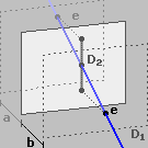
In the following example, the plane thickness is a + b. The projection distance away is a. The projection distance towards is b. D1 is the drillhole trace, and D2 is the trace orthogonally projected onto the plane. Point e shows where the drillhole trace exits the plane.
Task: Creating a temporary plane for graphical validation
- Open ore_solid1.dtm.
- Choose Planes > Vertical > Looking north.
- Move the slider and click at 7400.00.
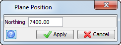
- Enter the information as shown, and click Apply.
- Click the Planes tab.
The Plane Position form appears.
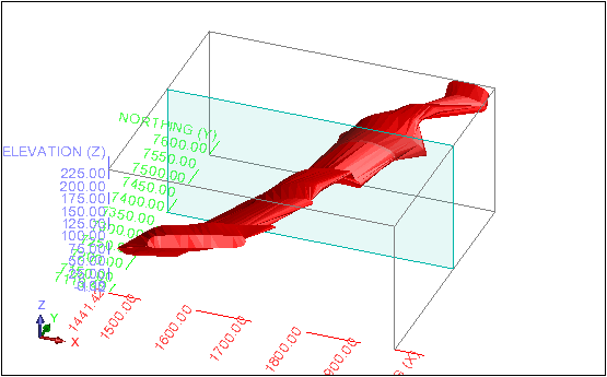
A temporary plane is created at 7400 N.
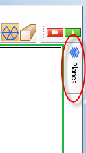
The Planes panel is displayed. Because the plane you have created is temporary it is not listed in the Planes panel.
Task: Saving a plane
- Choose Planes > Save current plane as.
- Enter the information as shown and click Apply.
- Click the Planes tab.
The New plane form appears.
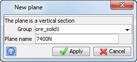
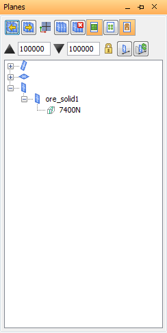
The plane is saved.
The Planes panel is displayed. Because the plane you have created is saved, it is listed on the Planes panel.
Task: Pinning the Planes panel to Surpac
- Click the Planes tab.
- Click the pin icon.

The Planes panel is pinned to the interface, and the pin icon is oriented down. The Planes panel remains to the right of Graphics regardless of the position of the cursor.
Task: Loading a plane from the Planes panel
- Click Reset graphics
 .
. - Open ore_solid1.dtm.
- In the Planes panel, right-click 7400N, and choose Set active.
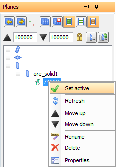
7400N is the active plane.
 Note: Plane 7400N has a check mark on the plane icon to show that it is the active plane.
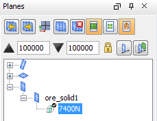
Task: Identifying the active plane using the Status bar
- Click Reset graphics .
- Look at the Status bar.
- In the Planes panel, right-click 7400N, and choose Set active.
- Look at the Status bar.
The plane is Dynamic.
7400N is now the active plane.
The plane name has changed to 7400N.

Task: Creating planes using Quick planes
- Choose Planes > Quick planes.
- Enter the information as shown, and click Apply.
The Quick Planes form appears.
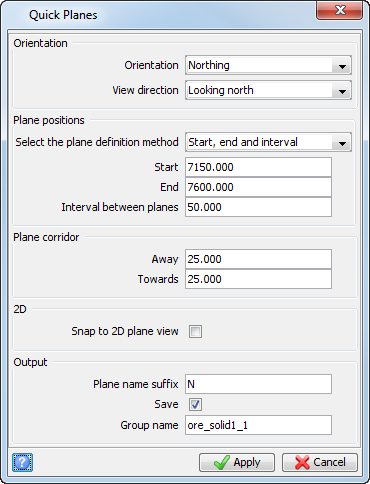
The plane group is listed in the Planes panel.
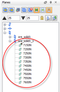
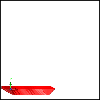
The first plane in the sequence is displayed in Graphics.
Task: Moving between planes
- In the Planes panel, click the Next Plane and Previous plane buttons
 .
. - Press F11.
- Press F12.
The previous plane is displayed.
The next plane is displayed.
Task: Viewing and changing plane properties
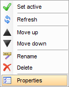
- In the Planes panel, right-click 7300N.
- Choose Properties.
- Type 1100 for the Sequence number, and click Apply.
- In the Planes panel, right-click 7200N.
- Choose Properties.
- In the Away field, type 50.
- In the Toward field, type 50.
- Click Apply.
- In the Planes panel, right-click 7200N and select Set active.
- Press F12.
The Vertical Plane Properties form appears.
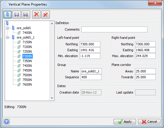
Notice that the sequence number for the plan is 400, and that the plane is the fourth in the group.
Plane 7300N is now listed last in the group.
The Vertial Plane Properties form appears.
The plane corridor is now 100 units wide.
Plane 7250N is now active. Notice that plane 7250N is still 50 units wide. The change you made was to the width of only plane 7200N.
Note: To modify the properties for every plane in the group in one action, right-click on the plane group and choose Properties.
Task: Changing the viewing corridor using the Planes panel
- In the Planes panel, right-click 7400N, and choose Set active.
- In the Away field
 , type 50.
 - In the Towards field
 , type 100, and click out of the field.
 - Press F12.
- In the Away field, type 50.
- In the Towards field, type 100.
- Click Lock plane corridor
 .
. - Press F12.
The view corridor is changed to display the data 50 units away from the view, and 100 units towards the view.
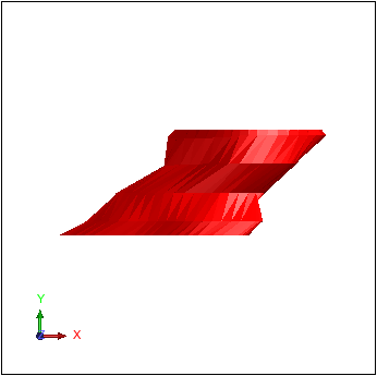
Plane 7450N is displayed with the default viewing corridor.
Plane 7500N is displayed with a viewing corridor that contains the data 50 units away from the view, and 100 units towards the view.