


Orbit mode
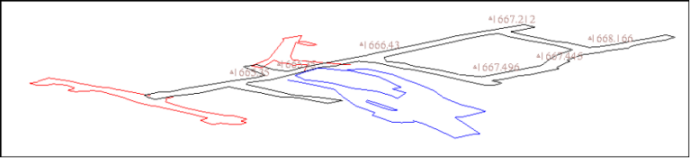
Orbit mode is the default Graphics mode, where you can rotate data in three dimensions. When you are using the orbit tool, Surpac operates in function-centric mode.
Task: Use orbit mode to rotate data
- Click Reset graphics
 .
. - Open survey1665.str in Graphics.
- On the Tools toolbar
 , click the Orbit tool
  .
. - Click and drag in Graphics to rotate the data.
The data rotates in three dimensions.
Selection modes
There are several ways of selecting data:
-
 Select mode
 -
 Point/Triangle mode
 -
 Segment/Trisolation mode
 -
 String/Object mode
 -
 Box selection
When you use any of these section tools, Surpac operates in data-centric mode.
Task: Change selection modes
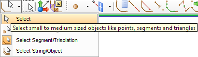
- On the Tools toolbar , click the drop-down triangle
 on the Select tool .
 - Click Select Point/Triangle.
- Click the Select tool (not the drop-down triangle ).
- Click the Select tool again.
- Click the Select tool icon again.
- On the Tools toolbar , click the Box selection icon .
- Right-click anywhere in Graphics to display a shortcut menu.
- At the bottom of the menu, click the Select tool .
- Right-click anywhere in Graphics to display a shortcut menu.
- At the bottom of the shortcut menu, click the Orbit view tool.
- On the Tools toolbar, click the Select tool .
- Press the ESC key.
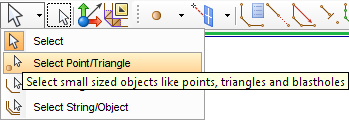
The Select tool now displays the Point/Triangle selection mode .
The icon now displays Segment/Trisolation selection mode .
The icon now displays String/Object selection mode .
The icon now displays Select selection mode .
The Tools toolbar now displays Box selection mode:  .
.
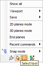
The Tools toolbar now displays Select selection mode  .
.
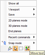
The Tools toolbar now displays Orbit view mode .
The Tools toolbar now displays Select selection mode .
The Tools toolbar now displays the Orbit view mode .
Task: Use point/triangle mode to delete points
- Click Reset graphics .
- Open survey1665.str in Graphics.
- From the Selection menu on the Tools toolbar, click Select Point/Triangle.
- Click the point as shown.
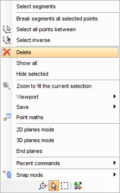
- Right-click anywhere in Graphics to display a shortcut menu.
- From the shortcut menu, select Delete.
- Hold the CTRL key, and click the points as shown.
- Press the DELETE key.
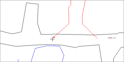
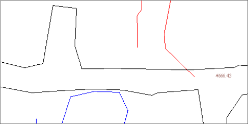
The point is deleted.
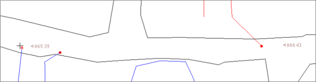
The points are deleted.
Task: Use segment/trisolation mode to reverse segments
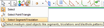
- From the Selection menu on the Tools toolbar, click Select Segment/Trisolation.
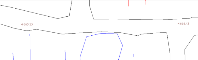
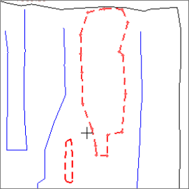
- Hold the CTRL key, and click the segments as shown.
- Right-click anywhere in Graphics to display a shortcut menu.
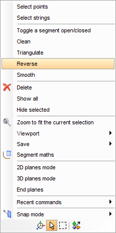
- From the shortcut menu, select Reverse.
The new segment directions are displayed in the message window.
|
String 2 Segment 1 is now Anti-clockwise String 2 Segment 3 is now Anti-clockwise |
Task: Use select mode to break, join, and renumber segments
With select mode, you can select either points or segments. This mode allows you to perform many string editing tasks quickly.
- Choose Display > Point > Numbers.
- Enter the information as shown, and click Apply.
- From the Selection menu on the Tools toolbar, click Select.
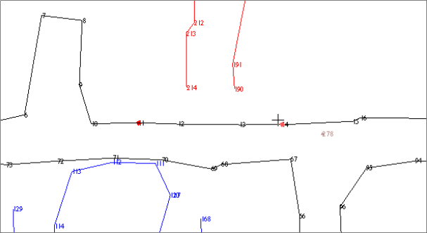
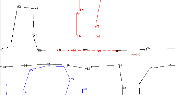
- Hold the CTRL key, and click points 11 and 14.
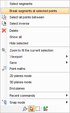
- Right-click anywhere in Graphics to display a shortcut menu.
- From the menu, select Break segments at selected points.
- Click at a location between the two points on the segment to be deleted, as shown.
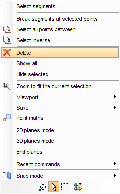
- Right-click anywhere in Graphics and select Delete from the shortcut menu.
- Hold the CTRL key, and select two points to be joined (105 and 216).
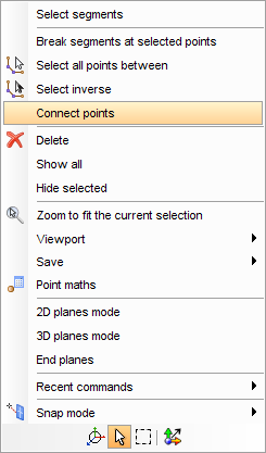
- Right-click anywhere in Graphics and select Connect points from the shortcut menu.
- Hold the CTRL key, and select two points to be joined (130 and 25).
- Right-click anywhere in Graphicsand select Connect points from the menu.
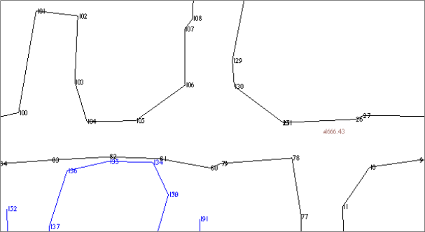
- Repeat steps 4 to 12 for other locations, until you get the final result is as displayed below.
- Choose Display > Strings > With string numbers.
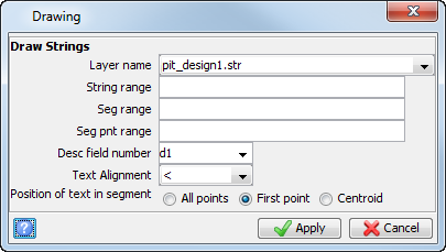
- Enter the information as shown, and click Apply.
- Click at a location between two points on the segment that you will renumber.
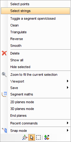
- Right-click anywhere in Graphics and choose Select strings from the shortcut menu.
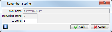
- Choose Edit > String > Renumber.
- Enter the information as shown, and click Apply.
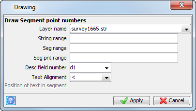
Point numbers are displayed.
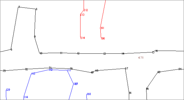
 Note: It is not necessary to display point numbers. This is only done to clearly identify points that you will select in the following steps.
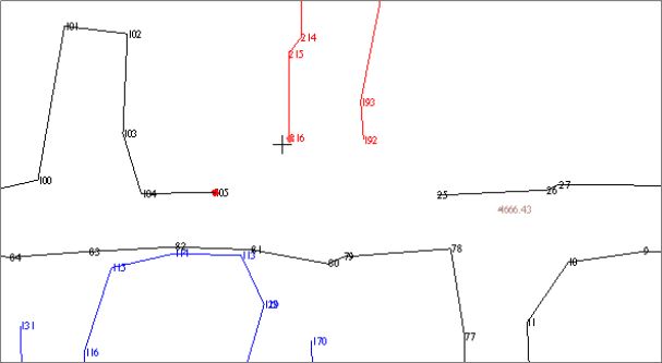
Note: If two segments of different string numbers are connected, the string number of the first point selected is used for the result. In the preceding example, if point 105 is selected first, then the resulting string number will be 1. If point 216 was selected first, the resulting string number will be 8.
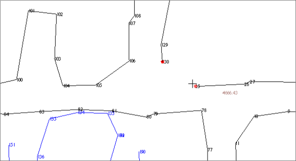
The points are joined.
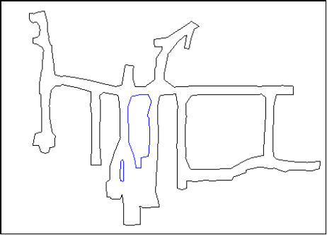
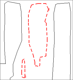
Next, you use the select tool to select and renumber all segments of string 2 to string 1.
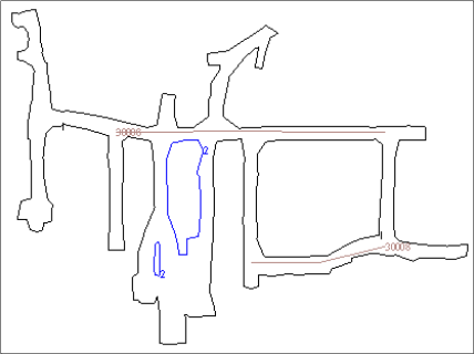
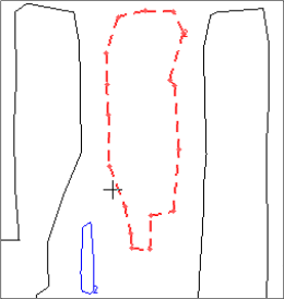
Both segments of string 2 are selected.
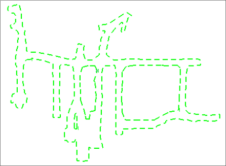
Task: Use string/object mode to delete and clean strings
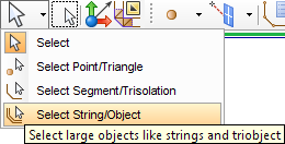
- From the Selection menu on the Tools toolbar, click Select String/Object
- Click string 30008 as shown.
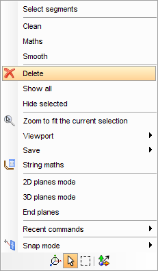
- Right-click anywhere in Graphics and select Delete from the shortcut menu.
- Click string 1, as shown.
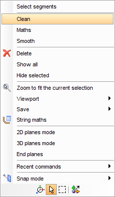
- Right-click anywhere in Graphics and select Clean from the shortcut menu.
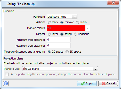
- Enter the information as shown, and click Apply.
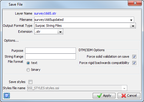
- Choose File > Save as.
- Enter the information as shown, and click Apply.
The Move tool
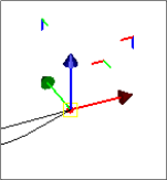
After you select data, you can use the Move Tool to move it:
- constrained along an axis
- constrained in a plane
- unconstrained
Task: Move data along an axis
- Click Reset graphics.
- Open lev1665.str in Graphics.
- From the Selection menu on the Tools toolbar, click Select Point/Triangle.
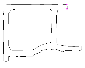
- Hole the CTRL key, and click the two points as shown.
- From the Tools toolbar,
 click the Move Tool
  .
. - Click and drag the X axis (red), as shown:
|
Before |
After |
|---|---|
|
|
|
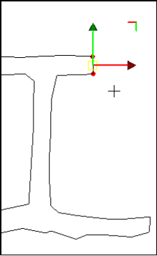
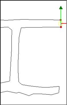
The Status bar displays coordinate values as well as the movement.

Task: Move data in a plane
- Click Reset graphics .
- Enter the information as shown, and click Apply.
- Open ore1.str in Graphics.
- Rotate the data as shown in the image in step 6 below.
- From the Selection menu on the Tools toolbar, click Select Segment/Trisolation.
- Click the segment as shown.
- On the Tools toolbar, click the Move Tool icon .
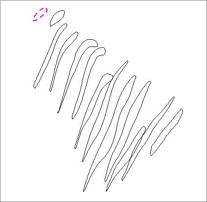
- Click and drag the red and blue corner to constrain the movement to the XZ plane.
- Click Reset graphics .
- Enter the information as shown, and click Apply.
|
Before |
After |
|---|---|
|
|
|
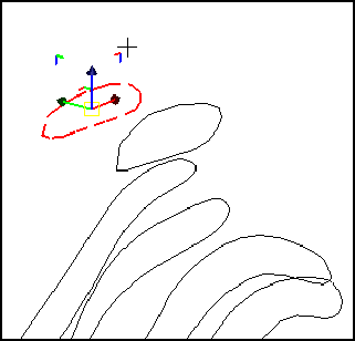
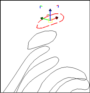
Only the X and Z values in the Status bar change as you move the segment.

Task: Move data in three dimensions
- Click Reset graphics .
- Open und1.str in Graphics.
- Open und_layout.str in Graphics.
- Click and drag in Graphics to rotate the data as shown.
- From the Selection menu on the Tools toolbar, click Select String/Object.
- Click the string in und_layout.str.
- Right-click and select the Move Tool from the shortcut menu.
- Click inside the yellow square at the intersection of the three axes and move the string as shown.
- Click Reset graphics .
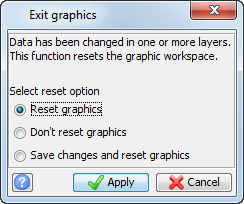
- Enter the information as shown, and click Apply.
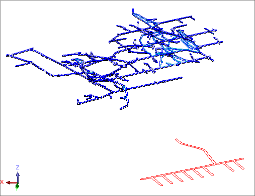
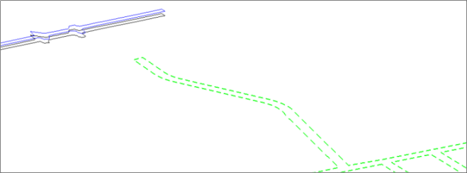
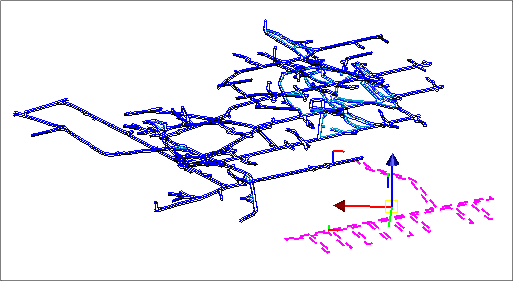
All three coordinates in the Status bar change as you move the string.