Creating data
Create a simple pit design
You will design a pit base around an ore zone at an elevation of 150, and then extend it up to an elevation of 250 with a pit wall angle of 45 degrees.
Task: Create a simple pit design
- Click Reset graphics
 .
. - Open ore150.str in Graphics.
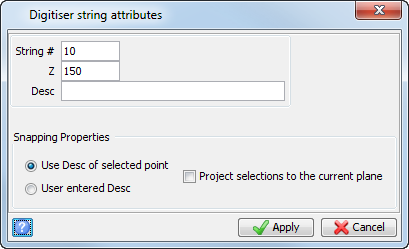
- Choose Create > Digitise > Properties.
- Enter the information as shown, and click Apply.
- Choose Create > Digitise > New point.
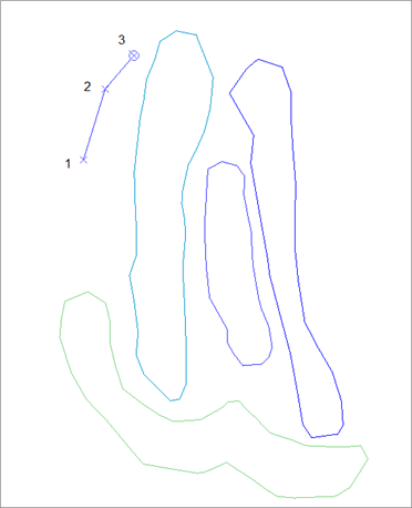
- Click in Graphics to create points 1, 2, and 3 as shown.
-
Do not press ESC. You have not finished creating the string.
- Numbers 1, 2, and 3 are not displayed in Graphics. They are shown on the images so you know the order in which to create the points.
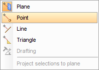
- Right-click in Graphics and select Point.
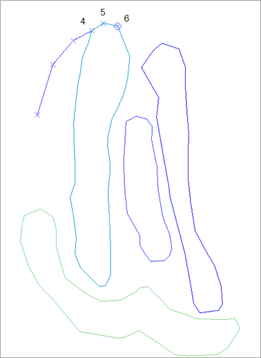
- Click three points at the northern end of the segment as shown, to create points 4, 5, and 6.
- Choose Create > Digitise > By following a segment.
- Click and hold down the left mouse button at point 7, then drag to point 8 and release.
- Click and hold down the left mouse button at point 9, then drag to point 10 and release.
- Choose Create > Digitise > Close current segment.
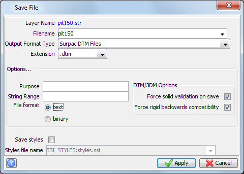
- Choose File > Save > string/DTM.
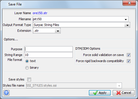
- Enter the information as shown, and then click Apply.
- Click Reset graphics .
- Open pit150.str in Graphics.
- Choose Display > Point > Numbers.
- Enter the information as shown, and click Apply.
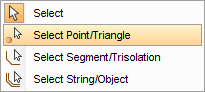
- Set the selection mode to Select Point/Triangle.
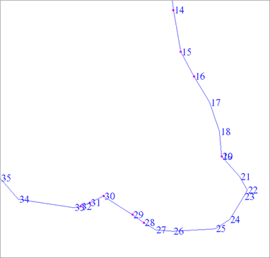
- Hold the CTRL key and click several points as shown.
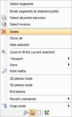
- Right-click in Graphics to display a shortcut menu, and select Delete.
- Choose Design > Pit design > Set slope gradient.
- Enter the information as shown, and click Apply.
- From the Status bar at the bottom of the Surpac window, click the
Design string button
 .
. - Enter the information as shown, and click Apply.
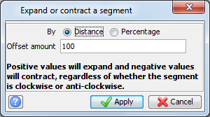
- Choose Edit > Segment > Expand/Contract.
- Click anywhere in Graphics to select the segment for expanding.
- Enter the information as shown, and click Apply.
- Press ESC to finish expanding.
- Hold down the right mouse button and drag down or to the left to zoom out.
- Click the Plan View button
 .
.
- Choose Display > Dynamic 2D Grid.
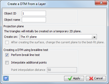
- Choose Surfaces > Create DTM from Layer.
- Enter the information as shown, and click Apply.
- Choose Display > Hide grid.
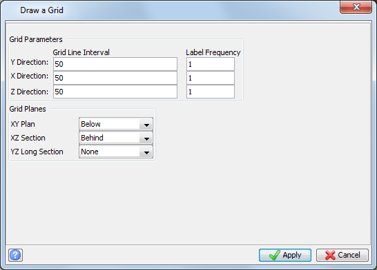
- Choose Display > 3D Grid.
- Enter the information as shown, and click Apply.
- To rotate the data, choose Planes > 2D planes mode, then click and drag in Graphics.
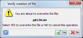
- Choose File > Save > string/DTM.
- Enter the information as shown, and click Apply.
- In the verification form, click Yes.
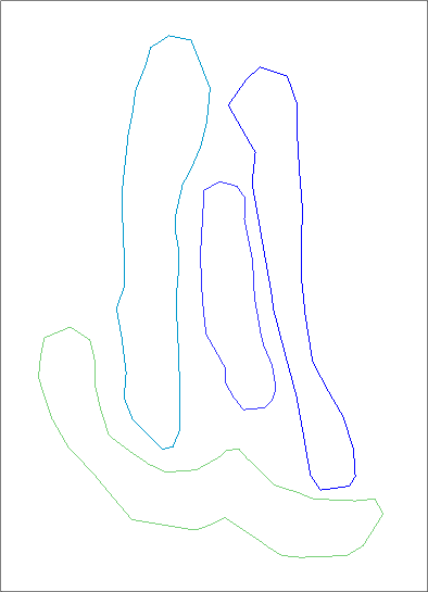
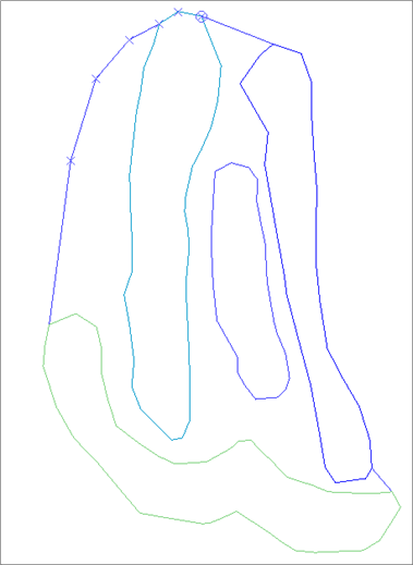
You can see a horizontal slice of ore zones at an elevation of 150.
 Notes:
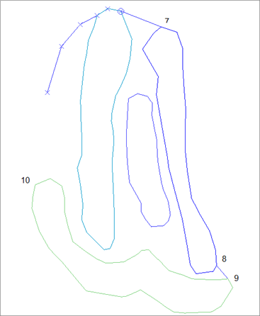
The closed segment is displayed.
Note: When you create closed segments in the XY plane (plan view), you will usually create them in a clockwise direction. Clockwise segments are regarded as an area of inclusion, and give expected results when you intersect them with other clockwise segments.
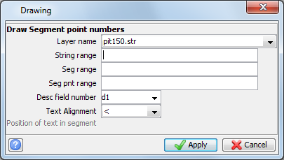
The numbered points on the segment are displayed.
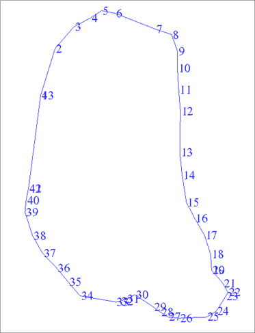
Next, you will delete some points to make the outline more convex.
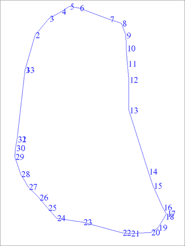
The renumbered segment is displayed.
Next, you will set the slope wall angle to 45 degrees.
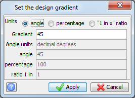
The Design grade button
 displays the current design gradient.
Next, you will set the string number for the top of the pit.
Note: This
step is optional.
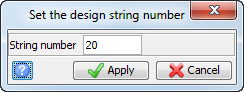
The Design string button displays the current design string number
 .
.
Next, you will expand the segment horizontally by a distance of 100. At an angle of 45 degrees, this will create a pit crest 100 meters above the base, at an elevation of 250.
The segments representing the top and bottom of the pit are displayed.
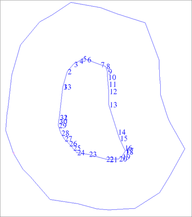
The pit strings and the Dynamic 2D grid are displayed.
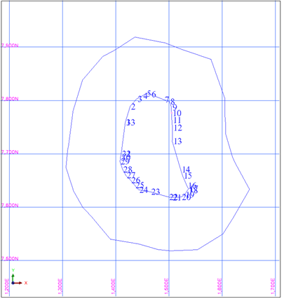
This procedure can be useful for determining the limits of a block model.
Next, you will create a DTM from this data.
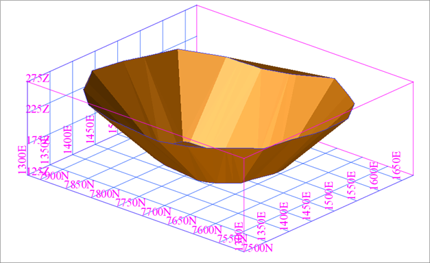
The pit and 3D grid are displayed.
Next, you will save the DTM file.