


Drill and blast concepts
There are several terms and concepts specific to this tutorial that are explained in this chapter. Not all terms are the same in all countries, and you might need to apply your preferred terminology in some cases. A lot of the terminology used in this document is specific to the mining and quarrying industries.
Drilling
Drilling parameters that you can customise include:
Bearing – also referred to as azimuth.
Burden – the distance between rows.
Collar – the starting point of a drill hole.
Diameter – the diameter of drill hole in units of measure (that is, metres or feet).
Dip – the angle of a hole above or below the horizontal.
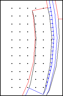
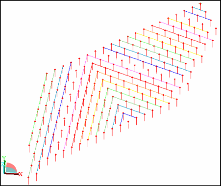
Pattern – a set of blast holes which will be collectively drilled, sampled, charged, and blasted.
An example of a pattern is shown below. Each dot represents one blast hole.
Spacing – the distance between holes in a row.
Subdrill distance – extra drilling length to add to each hole.
Toe – the bottom or ending point of a drill hole is referred to as the toe. A line defining the base point of a slope can also be referred to as a toe.
Presplit holes
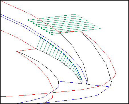
Often holes are drilled at closely spaced along a planned fracture plane. These holes are referred to in Surpac as presplit holes. Surpac can create presplit holes along a straight line or along a segment. The following example shows presplit holes created along a segment, and in a straight line. One set of holes is created from one segment, the crest of a bench, to another segment, the toe of the ramp. The horizontal holes, which could be used as drains in a pit wall, or for sampling, were created along a straight line.
Blast boundary
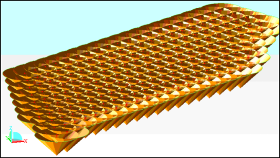
You can generate a blast boundary for a designed pattern using blast cones around each drill hole. The outermost segments of each cone are joined to create the blast boundary.
Blast solid
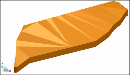
You can generate a blast solid by using the blast boundary and projecting it down to a design elevation or to a DTM surface.
Tie in patterns
You can generate a tie in pattern using one of the standard templates, or you can select holes/tie in lines individually to generate a customised pattern.
Blasting
Charging parameters which you can customise include:
Booster name – can be selected from Anzomex G (PG), Anzomex H (PH), Anzomex K (PK), Anzomex P (PPE), Anzomex PP D (PPD), Anzomex PP P (PPPE), Jumbo prime (PJ) or Stopeprime (PSP DL).
Charge depth – can be automatically adjusted to hole depth.
Charge interval – multiple charge intervals separated by stemming are allowed.
Database – all of the drilling and blasting information for each hole can be saved to a database. Surpac supports Access, and any database connectable via ODBC (Open DataBase Connectivity). The recommended database type is Access.
Delay time– the delay time in milliseconds, the default is 400 milliseconds.
Depth of stemming – rock chips, dirt, or other non-explosive material placed on top of the charge.
Detonator name – can be selected from Excel LP, Nonel LP, Nonel MS, connectadet, or enduradet.
Detonator position in the hole – can be selected from top, middle, or bottom of the hole.
Explosive – can be selected from ANFO 0.8, 0.9 or 1.0, Power Gel, air, or stemming.
Reports and volume calculations
You can generate three types of reports using the drill and blast functions:
- Blast summary – contains a rundown of all the blast design and costing details, including total drilling length, explosive products, mass of explosive down each hole, powder factor, blast volume, drilling cost, and explosive cost.
- Pattern setout – contains a list of hole numbers and their coordinates.
- Work order – contains details of the total number of explosive products to be used in a blast, including the number and type of detonators in the blast, total mass of explosive, kilograms of explosive per hole, and number of boosters required.