


Creating pre-split holes
Task: Create pre-split holes along a segment
- Click Reset graphics
 .
. - Open bench940.str in Graphics.
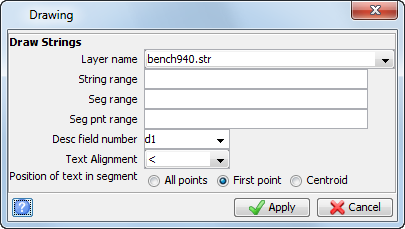
- Choose Display > Strings > With string numbers.
- Enter the information as shown, and click Apply.
- Click
 to see the data in plan view.
 - Zoom in on the ramp area, as shown.
- Choose Blast design > Pre-split holes along a segment.
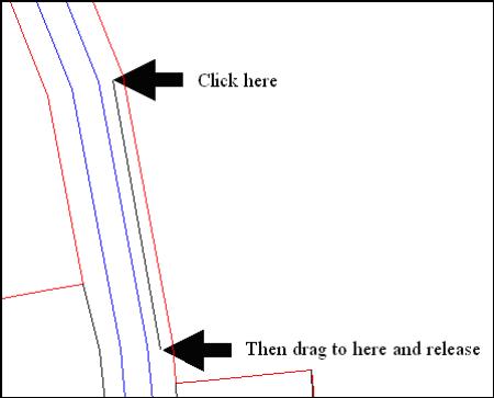
- Click the 950 crest as shown, drag to the top of the ramp, and then release the mouse button.
- Enter the information as shown, and click Apply.
- Select the ramp string as shown.
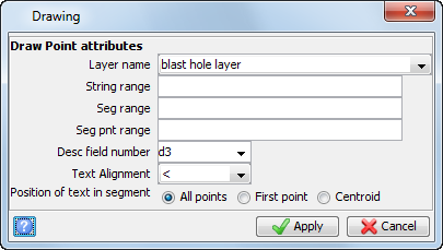
- Choose Display > Point > Attributes.
- Enter the information as shown, and click Apply.
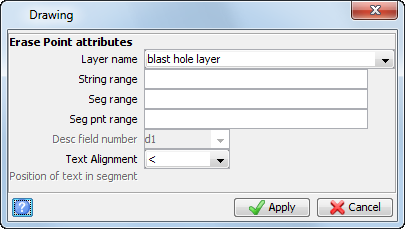
- Choose Display > Hide point > Attributes.
- Enter the information as shown, and click Apply.
- Rotate the data in Graphics.
- Choose Inquire > Point properties and click on the collars and toes of some holes.
- Choose Display > Point > Attributes.
- Enter the information as shown, and click Apply.
- Click .
- Zoom in on the southern end of the presplit holes.
- Choose Delete > Single hole.
- Click all holes less than 1.5 meters in length, and then press ESC.
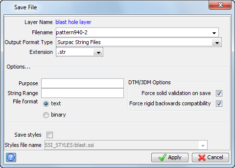
- Choose File > Save > string/DTM.
- Enter the information as shown, and click Apply.
The pit and ramp strings are displayed.
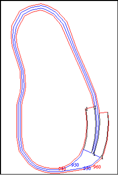
Notice that the following string numbers are used:
|
String |
Description |
|
1 |
ramp strings |
|
940 |
940 elevation design toe |
|
950 |
950 elevation design toe and crest |
|
960 |
960 elevation design crest |
You will create a pattern near the ramp from the 950 elevation to the toe of the ramp.
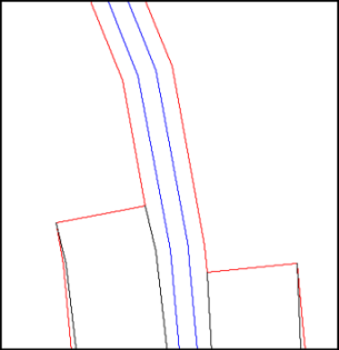
You will create the Pre-split holes on the ramp as displayed.
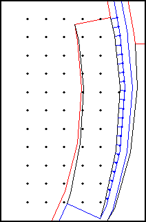
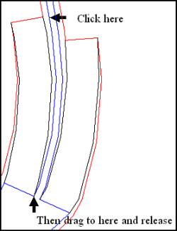
 Note: If, as you were dragging, any other segment was highlighted, you might have selected a different string. If any other string was selected, press ESC and perform this step again.
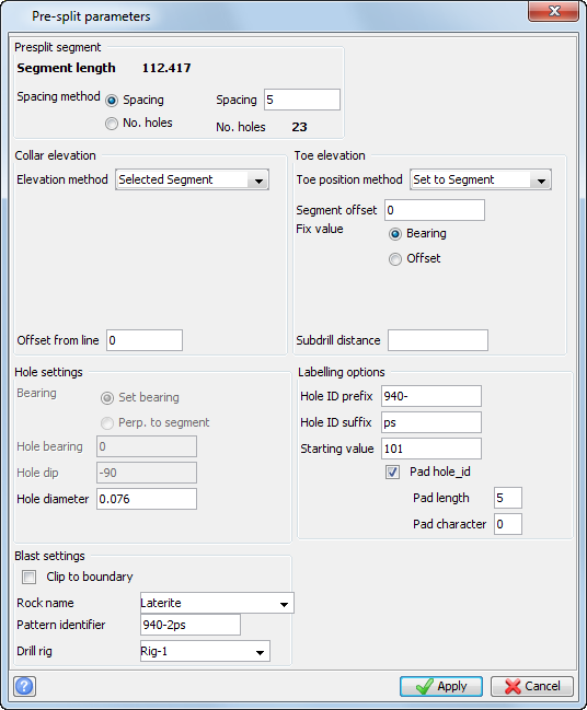
After applying the previous form, you will be prompted to select a target segment which will be used as the toe position.
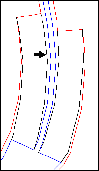
You will see the presplit holes created.
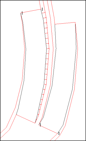
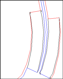
The ramp and numbered holes are displayed.
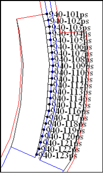
Note: The holes are numbered with the prefix 940-, suffix of "ps", and are drilled from the 950 crest down to the ramp toe.
The result is a series of two-point segments in the layer blast hole layer, which represent individual holes. The first point of the segment is at the collar, and the second point of the segment is the toe, or end of the hole. If the layer blast hole layer does not exist, it is created. If there are no strings in the blast hole layer, or if the blast hole layer does not exist, the string number used for the holes will be the design string number. If there are strings in the blast hole layer, the string number assigned to the holes will be one greater than the maximum string number.
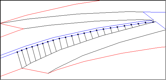
The ramp with holes is displayed.
The following data is present in the string file:
|
D1 |
D2 |
D3 |
D4 |
D5 |
|
|
Collar (start of segment) |
DrillBlast1.1 |
Hole ID |
Hole Number |
Hole Length |
Diameter |
|
Toe (end of segment) |
blank |
blank |
blank |
blank |
blank |
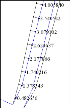
In this example, you want to make sure that you only create holes which are at least 1.5 meters long, because anything shorter is not worth blasting.

You can see that at least one hole is less than 1.5 meters in length.
Note: Your hole lengths will not be exactly the same as those displayed in the following image.
Note: To see all of the steps performed in this task, run macro
06a_presplit_holes_segment.tcl . You need to click Apply on any forms presented.
Task: Create pre-split holes along a straight line
- Click Reset graphics.
- Open bench940.str in Graphics.
- Choose Display > Strings > With string numbers.
- Enter the information as shown, and click Apply.
- Rotate the data in Graphics and zoom in and out to become familiar with the contents of the file.
- Choose Surfaces > DTM File functions > Create DTM from string file.
- Enter the information as shown, and click Apply.
- Close the log file.
- Click to return to plan view.
- Zoom in on the northern end of the two ramps, as shown.
- Choose Blast design > Pre-split holes along a line.
- Click a point approximately halfway between the 960 crest and the 950 toe as shown, drag to a point just south of there, then release the mouse button.
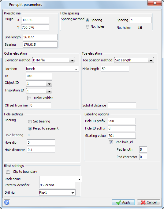
- Enter the information as shown, and click Apply.
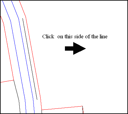
- Select a point to the east of the line as shown.
- Choose Display > Point > Attributes.
- Enter the information as shown, and click Apply.
- Rotate the data in Graphics.
- Choose File > Save > string/DTM.
- Enter the information as shown, and click Apply.
The pit and ramp with string numbers are displayed.
Notice that the following string numbers are used:
|
String |
Description |
|
1 |
ramp strings |
|
940 |
940 elevation design toe |
|
950 |
950 elevation design toe and crest |
|
960 |
960 elevation design crest |
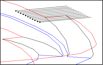
In this example, you will create horizontal drain holes on the pit wall.
The horizontal holes are as displayed.
You will use a DTM of the pit wall in this area to set the elevation of the holes.
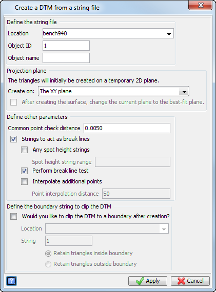
Note: You do not need to display the file in Graphics to use it to create holes.
A log file for the DTM opens in your defaul text editor.
Note: If you have any problems,
you can press ESC and try again.
Note: The coordinates of your Presplit line Origin, Line Length, and Bearing will be different, but should be of similar magnitude.
You are using a DTM file to set the collar elevations. The elevation of the holes created will be equal to the elevation of the DTM at the given XY coordinates of each hole. You are setting the bearing of the holes to be perpendicular to the segment (that is, perpendicular to the line you created). By setting the hole dip to zero degrees, you are creating horizontal holes. The holes will be numbered 950-701d, 950-702d, 950-703d, incrementing one for each additional hole.
After applying the Pre-split parameters form, you are prompted to select the direction in which the holes will be drilled.

Horizontal holes with numbers are displayed:
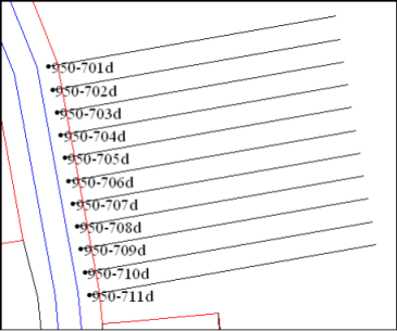
Note: The holes are numbered with the prefix 950-, suffix of "d", start at hole 701, and are horizontal.
The result is a series of two-point segments in the layer "blast hole layer", which represent individual holes. The first point of the segment is at the collar, and the second point of the segment is the toe, or end of the hole. If the layer "blast hole layer" does not exist, it is created. If there are no strings in the blast hole layer, or if the blast hole layer does not exist, the string number used for the holes will be the design string number. If there are strings in the blast hole layer, the string number assigned to the holes will be one greater than the maximum string number.
The horizontal holes are displayed.

Note: To see all of the steps performed in this task, run macro
06b_presplit_holes_line.tcl. You need to click Apply on any forms presented.