


Designing blast patterns using RMC polygons
Task: Design a blast pattern using auto spacing and burden from polygons
- Open bench960_950.str in Graphics.
- Open rmc_960.str in Graphics.
- Choose Blast Design > Create blast pattern.
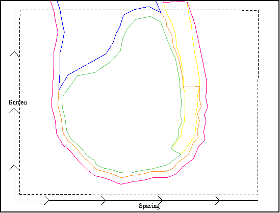
- Click and drag an area similar to that shown.
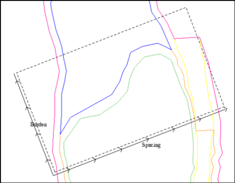
- Hold CTRL and left-click and drag to rotate the selected area as shown.
- Click and drag to move the selected area as shown.
- The blast pattern is aligned with the longest section of the free face.
- Press F2.
- On the Pattern settings tab, enter the information as shown.
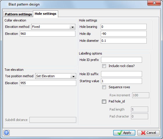
- Click the Hole Settings tab.
- Enter the information as shown, and click Apply.
- Choose Delete > Outside boundary.
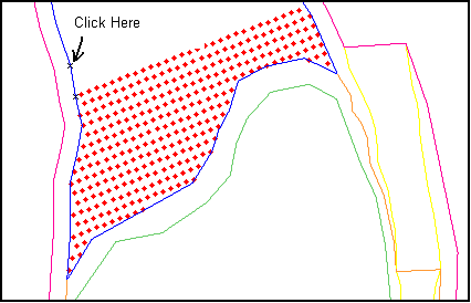
- Click any point on the top bench outline.
- Press ESC.
- Choose File > Save > string/DTM.
- Enter the information as shown, and click Apply.
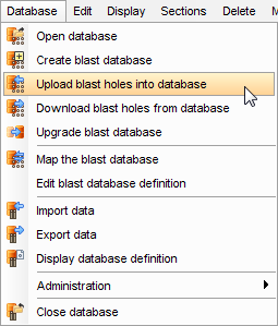
- Choose Database > Upload blast holes into database.
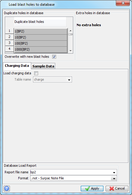
- Enter the information as shown, and click Apply.
- Enter the information as shown, and click Apply.
- When you mistakenly type in a duplicate Pattern Identifier on the Blast Pattern Design form. In this case, you should cancel the Load Blast Holes to Database form and edit the Pattern Identifier before continuing the Load Blast Holes to Database operation.
- When you have modified an existing pattern and now want to overwrite the original pattern stored in the blast database with new information.
- Enter the information as shown, and click Apply.
 Note: The polygon file must be in the active layer to use the auto spacing and burden from polygons option. This is why you open the polygon file into Graphics last.
You will design a blast pattern for the upper bench in the pit pickup, and align it with one section of the “free face”.
You are prompted to "Select area for blasting holes". In this case, you will select an area larger than you wish to blast and then trim the blast.
The Blast pattern design form is displayed.
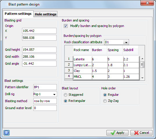
Note: The coordinates of the Blasting Grid Origin, Grid height, Grid width, and Grid angle will be different for you, but should be of similar magnitude.
A blast pattern is generated.
A prompt is displayed stating Select a closed segment.
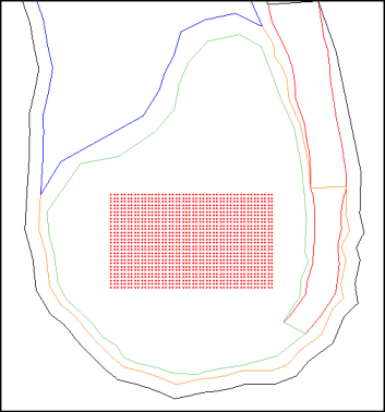
The trimmed blast pattern is displayed.
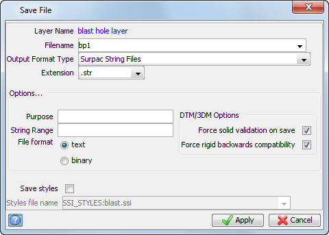
Note: After loading a blast pattern to the database, the string layer is deleted and holes from the database displayed. This is to avoid having two copies of the blast pattern in graphics at the same time, because if two layers were open they could contain conflicting information and cause an error. You do not have to save the string file, because you can download a pattern from a blast database back into string file format.
Note: Make sure you are using the blastdesign Database menu as shown, and not the one from the Geological Database menu.
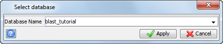
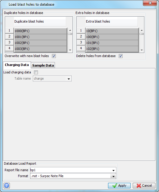
Note: There are two panels at the top of this form, Duplicate holes in database and Extra holes in database. These two panels warn you when a blast pattern with the same identification already exists in the blast database, and gives you the option of what to do.
There are two situations where you would have a duplicate blast pattern.
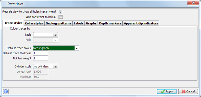
The drillholes are displayed.
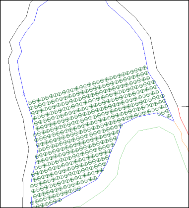
Task: Design a blast pattern with east/west orientation
- Click Reset graphics
 .
. - Open bench960_950.str in Graphics.
- Open rmc_955.str in Graphics.
- Choose Blast design > Create blast pattern.
- Create an area similar to that shown.
- Press F2.
- On the Pattern settings tab, enter the information as shown.
- Click the Hole settings tab.
- Enter the information as shown, and click Apply.
- Choose Database > Upload blast holes into database.
- Click Apply.
- Enter the information as shown, and click Apply.
- Click Apply on the Draw Holes form.
A prompt is displayed stating Select area for blasting holes.
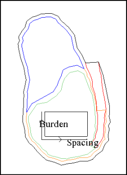
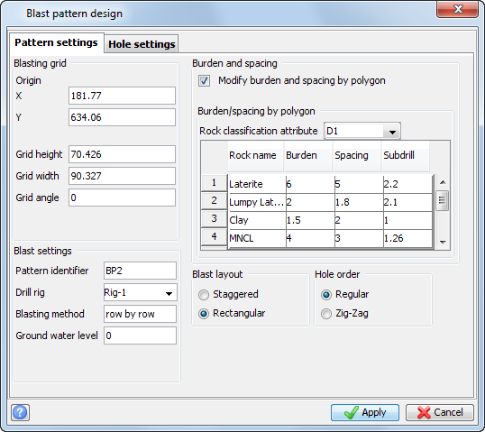
Note: The coordinates of the Blasting Grid Origin, Grid height, Grid width, and Grid angle will be different for you, but should be of similar magnitude.
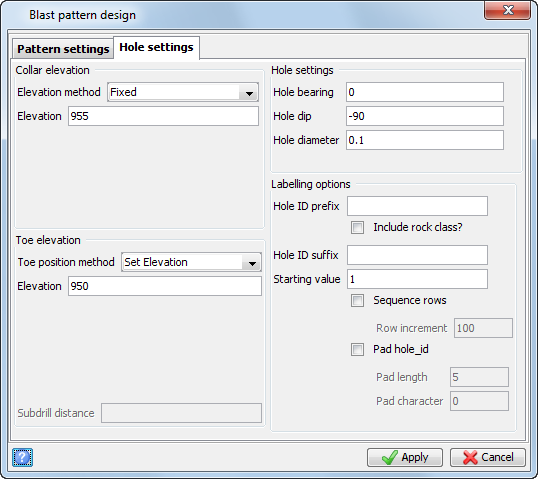
The blast pattern is displayed.
Note: Make sure you are using the blastdesign Database menu as shown, and not the one from the Geological Database menu.

The drillholes are displayed.
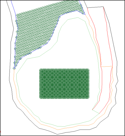
Note: Because you did not apply any constraints, all holes in the database are displayed, including bp1.
Task: Design a blast pattern with more than one burden and spacing
- Click Reset graphics.
- Open bench960_950.str in Graphics.
- Open multiple_rmc_zones.str in Graphics.
- Choose Blast design > Create blast pattern.
- Create an area similar to that shown.
- Press F2.
- On the Pattern settings tab, enter the information as shown.
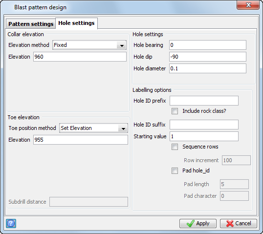
- Click the Hole settings tab.
- Enter the information as shown, and click Apply.
- Choose Delete > Outside boundary.
- Click any point on the top bench outline.
- Press ESC.
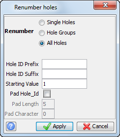
- Choose Blast Design > Renumber holes.
- Enter the information as shown, and then click Apply.
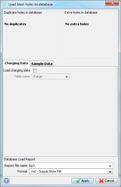
- Choose Database > Upload blast holes into database.
- Click Apply.
- Enter the information as shown, and click Apply.
- Click Apply on the Draw Holes form.
- Enter the information as shown, and click Apply.
A prompt is displayed stating Select area for blasting holes.
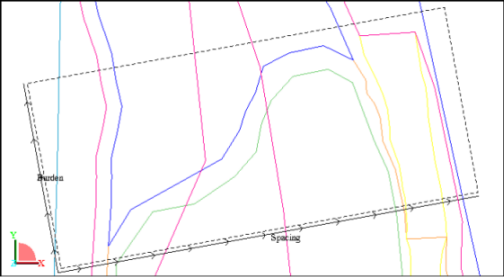
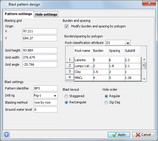
Note: The coordinates of the Blasting Grid Origin, Grid height, Grid width, and Grid angle will be different, but should be of similar magnitude.
A prompt is displayed stating Select a closed segment.
The blast zones are displayed:
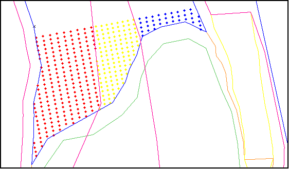
Note: You will need to edit some holes at the contact zone between different RMC areas, because the burden and spacing conditions cannot be met in all cases at these locations.
Note: Make sure you are using the blastdesign Database menu as shown, and not the one from the Geological Database menu.
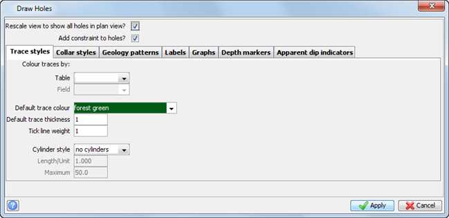
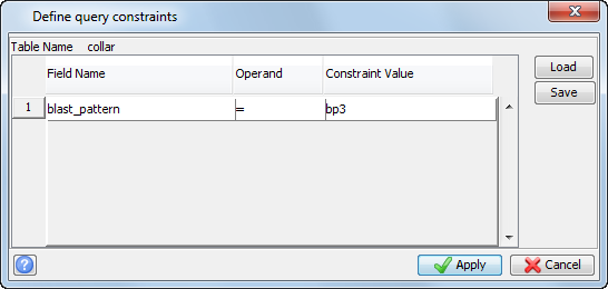
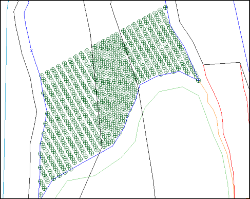
The drillholes are displayed.
Note: To see all of the steps performed in this section, run
02_auto_rmc_patterns.tcl . You need to click Apply on any forms presented.