


Creating a block model
Create a block model
Task: Create a block model
- Open ore1.dtm in Graphics.
- Choose View > Zoom > Out.
- Choose Display > 2D grid.
- Enter the information as shown, and click Apply.
- Click the
 icon to show the data in section view.
 - Choose Display > 2D grid.
- Enter the information as shown, and click Apply.
- Choose Block model > New / Open.
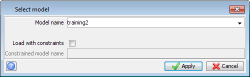
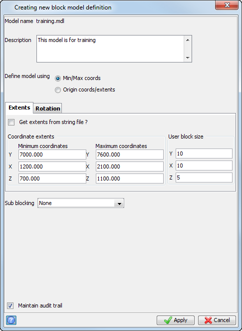
- Enter the information as shown, and click Apply.
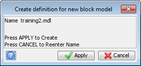
- Click Apply to confirm creation of the new block model.
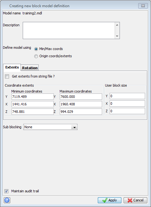
- Select the Get extents from string file box.
- In the Location box, type ore1, press TAB, and click Open.
- In the Description field type a description of the block model.
- Adjust the values as shown to create a block model which completely covers the extents of the ore body.
- Click Apply.
- Enter the information as shown, and click Create Model.
- Click Reset graphics
 .
. - Choose Block model > Save to save the block model.
- Choose Display > Display block model.
- Enter the information as shown, and click Apply.
- Rotate the view in Graphics.
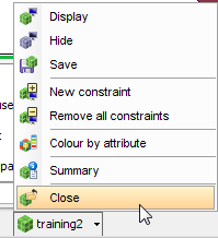
- Right-click the block model in the status bar, and choose Close
The solid of the ore body is displayed.
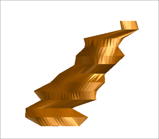
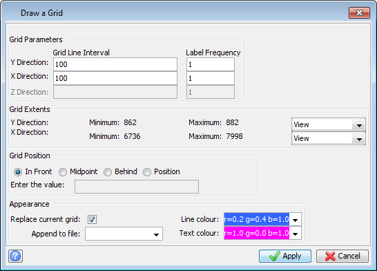
The ore body with the 2D grid in plan view is displayed.
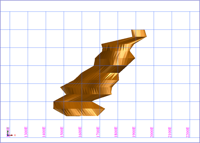
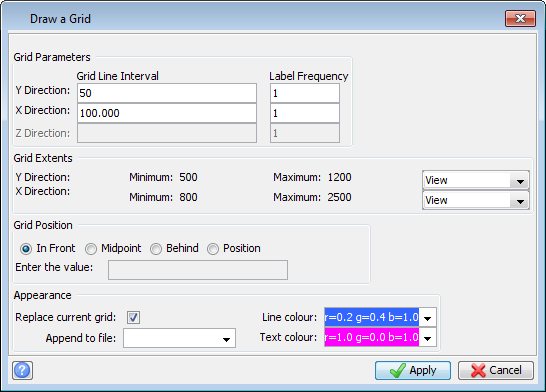
The ore body is displayed in section view with a 2D grid.
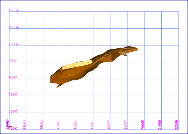
Using the previous diagrams, you can determine the origin and extents of the block model which will cover the ore solid.
You can also use the string file ore1.str to determine the origin and extents directly from the data. This method is described in the following steps.
The model's coordinates are filled in based on the values in ore1.str.
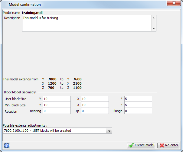
The block model is created and its name is displayed in the Status bar.

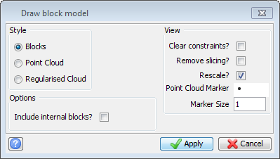
The block model is displayed.
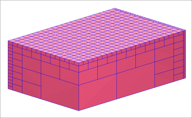
 .
.
 Note: To see all of the steps performed in this task run
_01_create_model.tcl. You will need to click Apply on any forms presented.
Note: To see all of the steps performed in this task run
_01_create_model.tcl. You will need to click Apply on any forms presented.