


Intersect trisolations commands
The intersection commands are:
| INTERSECT | |
|---|---|
| 3DM/3DM | |
| Union | Unions two 3DMs |
| Intersect | Intersects two 3DMs |
| Outersect | Outersects two 3DMs |
| 3DM/DTM | |
| Above | Saves the portion of the 3DM above the DTM and of the DTM which is inside the 3DM |
| Below | Saves the portion of the 3DM below the DTM and of the DTM which is inside the 3DM |
| Inside | Saves the portion of the DTM which is inside the 3DM |
| Outside | Saves the portion of the DTM which is outside the 3DM |
| DTM/DTM | |
| Upper | Constructs a new DTM of the uppermost triangles from the two source DTMs |
| Lower | Constructs a new DTM of the lowermost triangles from the two source DTMs |
| Intersect | Constructs a new 3DM by intersecting the two source DTMs |
Intersect Trisolations functions permit you to perform a variety of intersections between two 3DMs, two DTMs or a DTM and a 3DM to produce a new 3DM or DTM.
The use of the Intersect Trisolations functions involves recalling one or more .dtm files into graphics, running an intersection function, and using the mouse to select two trisolations. The line of intersection between the two trisolations is then found and the triangles lying across the line of intersection for each of the trisolations are split into subtriangles to ensure that the two trisolations can be joined smoothly. Finally the trisolations are combined, deleting unwanted triangles depending on the particular operation chosen. The resulting trisolations are displayed directly to the screen.
The Intersect Trisolations functions are useful for:
- determining the resultant solid when a decline is driven through an ore body
- modelling bifurcating ore bodies
- determining the volume of an ore body above and below a proposed pit surface
- combining new tunnels/drives with existing tunnel/drive networks
- determining the volume extracted from an ore body by a tunnel/drive
- combining a ground terrain profile with a proposed pit profile to determine the resulting combined profile and the volume of material which must be removed
- cutting ore bodies with fault planes
- combining a DTM representing a proposed pit surface and a DTM representing a topological ground profile to produce a new DTM of the ground profile containing the pit
- combining a DTM representing a proposed waste stockpile and a DTM representing a topological ground profile to produce a new DTM of the ground profile containing the stockpile
The result of the Intersect Trisolations functions may be a single trisolation or a set of multiple distinct trisolations. A set of distinct trisolations might occur, for example, when a decline is intersected with an ore body and the decline cuts through the ore body in several places. Where the result of an operation is a set of multiple distinct 3DMs or DTMs these are split into separate trisolations. This means that further operations can be performed on the individual trisolations. In the case where the result is multiple 3DMs the volumes of the multiple solids can be examined individually. The resultant trisolations have their neighbour lists set automatically, are automatically checked for validation, and in the case of 3dms, have their directions set to SOLID.
Intersect Trisolations functions erase the two source trisolations from the screen and replace them on the screen with the resultant trisolations.
Note:The two source trisolations are not deleted or changed and can easily be redisplayed using the DRAW OBJECTS function.
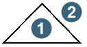
The Intersect Trisolations operations can be performed on 3DMs which have their directions set to either SOLID or VOID. It should be noted, however, that the definitions of 'inside' and 'outside' are different for solids and voids. This convention can be demonstrated by considering cross sections through two triangular prisms, the first a solid and the second a void:
|
1. inside 2. outside |
|
1. outside 2. inside |
| cross section through a solid triangular prism | cross section through a void triangular prism | ||
The Intersect Trisolations functions operate on the data stored in one or more .dtm files. The results are stored as an object in a user defined graphics layer, which can be stored in a new .dtm file if required.
Each Intersect Trisolations function requires:
- any DTM trisolations used to have been created by the CREATE DTM function (or by a previous application of an Intersect Trisolations function), this guarantees that the triangles in the DTM are all orientated correctly;
- the neighbours to have been set for the two trisolations, and 3DM trisolations to have validated=true;
- 3DM trisolations to be CLOSED and have their direction set to either SOLID or VOID;
- the line of intersection between the two trisolations to be closed (this is always the case with operations between two 3DMs but will not always be true for operations involving at least one DTM).