


Solids
3DM
A 3 Dimensional Model (3DM) is a solid formed by wrapping a surface (that is, a DTM) around two or more closed strings, A 3DM is an extension of the following concepts:
- a point
- a string
- a DTM (digital terrain model)
- a 3DM
Point
A point is a position in space whose YXZ coordinates are known.
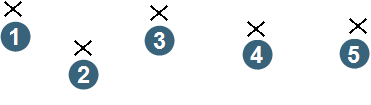
|
1.point 1 2. point 2 3. point 3 4. point 4 5. point 5 |
String
A string is a line joining a succession of points.

|
1. start of string 2. end of string |
DTM
A DTM is a surface joining adjacent strings. It is formed as a combination of those string lines, and lines joining points on adjacent strings. For example, the following image shows three adjacent strings from which the DTM is formed.
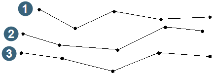
|
1. string 1 2. string 2 3. string 3 |
The joining continues until the surface consists only of non-overlapping triangles. The software chooses the joins to produce the best-conditioned triangles - that is, those closest to equilateral triangles.
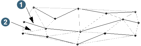
|
1. string line 2. join line between points |
The DTM is like an undulating patchwork quilt made of triangular patches.
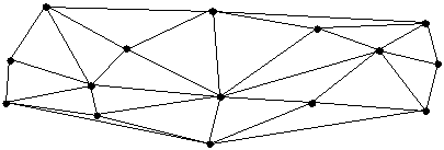
3DM
A 3DM is a solid formed by wrapping a DTM around closed strings that represent sections through the solid.
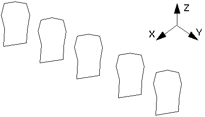
The 3DM is like a patchwork quilt (with triangular patches) that is wrapped around a series of wire frames (closed strings). For clarity, the sketch shows only the surfaces of the DTM facing you. In reality the 3DM covers all faces of the solid.
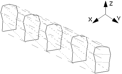
Thus a 3DM is the 3-dimensional extension of a conventional DTM. Just as a DTM defines a surface with a set of non-overlapping (in two dimensions) adjacent triangles, a 3DM defines an object with a set of non-overlapping (in three dimensions) adjacent triangles.
The distinction between the two kinds of model is:
- A DTM defines a surface.
Typical examples are coal seams, topographies, and grade distributions. The triangles are formed by connecting groups of three data points together, taking into account their spatial location in just the XY plane. A DTM allows for the extraction of contours, sections and the calculation of volumes between DTM's.
Creation of the DTM triangles is essentially automatic. But a limitation is that you cannot use a DTM to define a structure with overhangs or foldbacks.
- A 3DM defines a solid object or a void.
Typical examples are orebodies, stopes and development drives. A 3DM is generally used to define an object in a manner such that the triangles completely enclose the object. This allows for the extraction of closed outlines on a plane of intersection or the calculation of volumes inside the object.
Creation of the 3DM triangles is essentially interactive, although this is automated as much as possible.
3DM Concepts
The most common use of a 3DM is to define the boundary of an ore body.
An important property for any ore body model is the ability to extract horizontal slices and so give you plan view outlines of the ore body. This is because plan view outlines are very useful when planning and scheduling the layout of a mine.
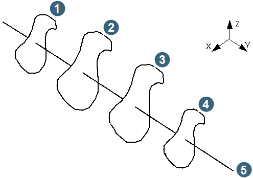
One conventional method of doing this is to use a sectional model - a set of parallel vertical sections with polygonal outlines defining the outline of the ore body at each section. The outlines are manually interpreted by a geologist using grade and structural information obtained from drill holes, and the geologist's interpretation of other geological features in the vicinity.
|
1. vertical section 1 2. vertical section 2 3. vertical section 3 4. vertical section 4 5. horizontal axis |
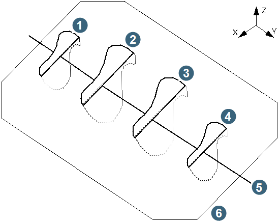
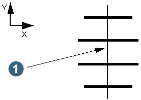
Although the sectional model works well enough for defining the ore body and estimating grades, it has deficiencies - all attributable to the 2.5-dimensional nature of the model. In particular, when you slice it horizontally you see only a series of lines, one per vertical section. For example, a horizontal slice through the previous ore body, like this:
|
1. vertical section 1 2. vertical section 2 3. vertical section 3 4. vertical section 4 5. horizontal axis 6. horizontal slice |
produces this plan view:
|
1. horizontal axis |
Since the data is unsuitable for computer interpretation as it is, a geologist must manually interpret the full plan outline before using the data for mine planning.
A 3DM may consist of a number of objects. These objects should be thought of as discrete features. For example, object 1 may be an ore body and object 2 may be a stope.
Each object may consist of a number of trisolations. Trisolations of an object should be thought of as isolated parts of the same features. For example, an ore body may have three discrete pods of ore.
An object trisolation may be either open or closed. The status of a trisolation (whether it is open or closed) is implicitly in the triangles which for the trisolation. If there is a gap in the triangle network which defines a trisolation then the trisolation is open, otherwise it is closed. Just one missing triangle is sufficient to open the trisolation.
An object may contain both open and closed trisolations.
The reasons for treating objects as open or closed are:
- a closed object can have its volume determined directly by summing the volumes of each of the triangles to an arbitrary datum plane.
- a closed object always produces closed strings when sliced by a plane.
- an open object cannot provide the same capabilities; when sliced by a plane the strings it produces may be open or closed or both.
A 3DM is formed by a combination of several techniques which go under the general name of stitching - that is, joining two things (two lines, or a line and a point) by 'stitching' lines back and forth between the two to form a set of adjacent triangles. The several techniques are:
- Stitching together pairs of adjacent strings defining the feature of interest. The strings are generally but not always on planes parallel to each other and separated by some distance. You have control over the stitching mechanism by defining matching control points on the pair of strings. The stitching is then performed between two pairs of control points at a time. The following image shows the process of stitching together string 1 and 2 in a series of five strings.
- Stitching a closed string to a single point by selecting the string and then the point from which the stitches are to radiate.
You generally use this technique to close the open face at each end of the object.
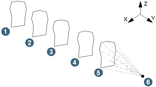
1. string 1
2. string 2
3. string 3
4. string 4
5. string 5
6. single point
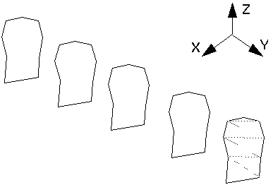
- Stitching a string in isolation by forming triangles between points on it.
The technique is generally used for formatting triangles within a drive outline, such as back and floor outlines.
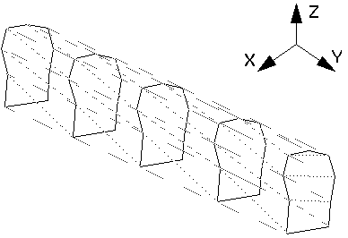
- Automatically stitching together a group of closed strings on different planes by defining one or more control strings that define the starting point for triangulation between each pair of strings.
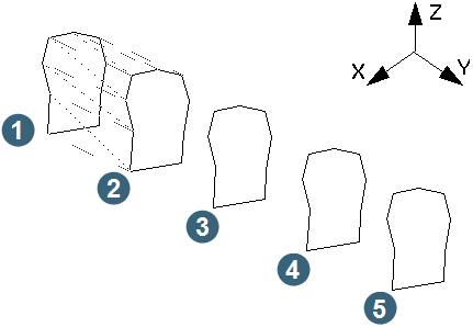
|
1. string 1 2. string 2 3. string 3 4. string 4 5. string 5 |
3DM Files
3DMs and DTM's are so closely related to each other that the method used to store them in files is the same. That is, a '.str' file and a '.dtm' file, both with the same location and ID number together represent the 3DMs. These files are ASCII text files which may be viewed or edited with a text editor. However, editing with a text editor is not recommended.
Even though two files are used to store the data they are linked together by the header record of the `.dtm' file. This header record defines the `.str' file to which the `.dtm' file is related and it also defines a checksum value which is used to ensure integrity between the `.dtm' and `.str' files.
An example header record from a `.dtm' file is shown below:
sto1200.str, 5861855100; algorithm = standard; fields = x,y
sto1200.strThis the name of the string file to which the `.dtm' file is related.
5861855100This is the checksum value which is used to validate the integrity of the `.str' and `.dtm' file relationship. The checksum is a value which is computed from the coordinates in the string file and it is written to the header record of the `.dtm' file when the `.dtm' file is created.
When a `.dtm' file is recalled for processing the checksum value which is stored is compared against a newly computed checksum value based on the current contents of the `.str' file. If there is a difference between the stored and computed checksum then the 3DM or DTM will not be loaded.
algorithm = standardThis defines the checksum algorithm which is to be used for the calculation of the checksum value. Currently, only the `standard' algorithm is used.
fields = x, yThis defines the fields from the string file which are used in computing the checksum.
The checksum is not a reliable method of ensuring consistency between the `.dtm' and `.str' files. It is designed to prevent mistakes by deleting gross errors in the data.
Object Identification
The objects you form are known to you by a numbering system analogous to that of string and string segment numbers.
When you define an object you explicitly assign it both an object number(also known as an object id) and a trisolation number. That object is then always referred to by the object and trisolation number originally assigned.
The object number/object id may be any integer in the range 1 to 32000.
The trisolation number may be any positive integer.
Extracting Slices from the 3DM
After forming a model, you can extract slices from it on a plane of any orientation or inclination, and save the slices in conventional `.str' files.
If a string in a slice is open, either:
- the object being sliced is open, or
- the object has overlapping triangles, caused by careless model formation.
You specify the slices to be extracted by defining an axis line and an interval along the axis line for each slice. The slices are extracted on planes normal to the axis line at the specified interval. The first slice is at the start of the axis line.
The axis line is defined by entering the Y, X, Z coordinates at the start of the axis and the Y, X, Z coordinates at the end of the axis. Definition of the axis in this manner allows the axis to have any orientation and inclination. This then makes it possible to extract slices on planes which are vertical, horizontal or inclined.
The strings produced have the same string number as the object from which they originated. It is possible therefore for a number of string segments to be produced for a single object trisolation when sliced by a plane as there could be any number of intersections with the plane.
Coordinates of Extracted Slices
The coordinates of the strings produced by extracting slices from a 3DM depend on the orientation of the axis you use. The rules governing the coordinates also relate to the ID numbers which are assigned to the files that contain the slices. This is because of the relationship between the Z value of the strings and the ID of the files. In the following explanation:
- YM, XM, ZM refer to the coordinates of the original 3DM, and
- YS, XS, ZS refer to the coordinates of the strings produced on the slices.
- The axis is vertical and rising from start to end That is, YA = YB XA = XB ZA < ZB
The result is a horizontal contour line as typically produced by contouring a DTM. In this situation the coordinates of the strings produced are in the same coordinate system as the model from which the slice is extracted:
that is, YS = YM XS = XM ZS = ZM
- The axis is horizontal and travelling from south to north.
That is, YA < YB XA = XB ZA= ZB
The result is a vertical cross section on an east-west line looking north. In this situation the coordinates of the strings produced are in the same coordinate system as the model from which the slice is extracted except that they are in a section view:
that is, YS = ZM XS = XM ZS = YM
- The axis is horizontal and travelling from east to west
That is, YA= YB XA < XB ZA= ZB
The result in this case is a vertical cross section on a north-south line looking west. In this situation the coordinates of the strings produced are in the same coordinate system as the model from which the slice is extracted except that they are in a section view:
that is, YS = ZM XS = YM ZS = XM
- The axis is horizontal but oblique to north-south and east-west axes.
That is, YA <> YB XA <> XB ZA= ZB
The coordinates of the resulting strings are relative to the axis line itself:
that is, YS = ZM
- The axis has an orientation which is none of the above.
That is, YA <> YB or XA <> XB or ZA <> ZB
The coordinates of the resulting strings are relative to the axis line itself:
that is,
YS = distance above or below the plane of the axis
XS = distance left or right of the axis
ZS = distance along the axis