Triangulate Between Connected Segments
Choose this function if you have two closed segments that are connected together, and you want to triangulate between them. This requirement comes up when dealing with large complication triangulations, and the triangulation needs to be done in a piece by piece way. If there are segments that are not connected together, then it is better off to do the triangulation with TRIANGULATE AUTOMATIC, rather than digitising the extra connections required for this function.
To run this function: Choose Solids > Triangulate > Connected segments > Between, or...
Two segments in the current layer, and all segments connected to them will be used to create triangles between the two segments. After creating the solid, you should validate the solid to check for errors in the triangulation. A valid solid will be formed when all segments cross at coincident points, and sufficient control strings exist. Invalid solids can be created when:
- Lines pass through or very near to points.
- Two or more points are very close to one another, but not coincident.
- Two lines intersect in 3D, but do not contain any points where they intersect.
These problems can be solved by ensuring that wherever two segments cross, they contain exactly coincident points. If all segments cross at coincident points, adding more control strings near the error can also help. Control strings can be open or closed, and be of any string or segment number and direction, but must be snapped to existing points.
An important thing to note is that you do not have to pick closed segments that are adjacent to each other. You can pick any two closed segments, and the connected parts between them will be triangulated. This makes triangulating many simple cross sections very quick and easy.
There are some general guidelines that should be followed to get the most out of this function. For a description of the algorithm used to create the triangulation, go here.
NOTE: The algorithm used uses a semi-random approach to producing the final triangulation. This will cause consecutive runs of the functions to potentially cause different results. If a particular data set is producing good results sometimes, and bad results other times, it is an indication that more control is required to consistently produce a good solid.
Form options
Object and Trisolation
The Object and Trisolation fields defined what object will be created.
Selection Method
- Graphical selection of the segments. With this method, you graphically select what segment to triangulate from and to. First you are prompted what segment to triangulate from, then you select the one to triangulate to. After those the triangulation is complete. Pressing ESC at any time will cancel the function and return to graphics.
- Segment range. This option allows you specify the String ID and segment number for the two segments to triangulate between. This can be very useful if you are writing a macro to automate a large number of triangulations.
Triangulation algorithm
This option is used to control the normal generating aspect of the triangulation procedure (described in detail here). This option is generally only turned off if you are having trouble creating a valid triangulation, and there are some difficult situations that the algorithm has to deal with. Some of these could be:
- The segments that connect the closed cross sections lie on exactly the same plane as that cross section. This makes some of the work incredibly difficult.
- There are more than four line segments coming out of any one point. This is a situation that should be avoided in general, but turning off this option may help.
Examples:
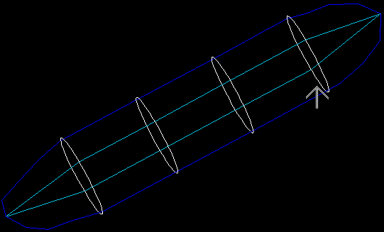
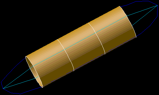
Graphical selection of two polygons (leaving solid open)
Select a segment to triangulate from
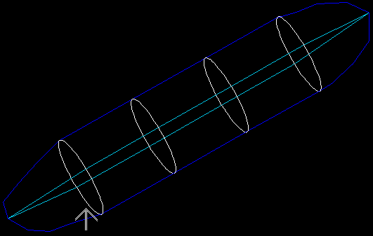
Select a segment to triangulate to