


Create DTM from layer
You can use this function to create a DTM from the data you have loaded in the active layer in Graphics.
To run this function: Choose Surfaces > Create DTM from layer, or...
Fields on the Create a DTM From a Layer form
| Field | Description |
|---|---|
| Object ID | The ID for the object in the new DTM. |
| Object Name | The name for the new DTM. |
| Projection plane | |
| Create on: |
The plane the DTM is created on. You can choose:
|
| After creating the surface, change the current plane to the best-fit plane |
|
| Creating a DTM using breakline test | |
| Perform break line test |
|
| Interpolate additional points |
|
| Point interpolation distance | If Interpolate additional points is selected, the distance at which new points are created. |
 Note: This option is not available if the active plane is the XY plane.
Output
A DTM is created in the active layer in Graphics. If crossing breaklines are identified, they are marked with red temporary markers at an elevation above the data in the active layer. The markers make it easy for you to see where the crossing breaklines are located.
 Tip: You can run the breakline test manually using the CLEAN LAYER function.
Troubleshooting
| Message | Description |
|---|---|
POINT nn WITH RL xx HAS SAME X,Y AS POINT ii WITH RL yy NOT FATAL
|
Points with the same X, Y coordinates and different Z coordinates will be replaced with one point, the Z coordinate being the mean value. |
|
|
These error messages indicate an error occured during the creation of the surface where the geometric arrangement of strings, segments, and points is such that it is not possible to create a surface.
|
Error applying breakline to triangles. See warning messages for details.
|
A problem has occurred when adding a break line to the DTM surface. The warning messages indicate the location of the problem. |
Errors
| Error | Description | Solution |
|---|---|---|
|
||
|
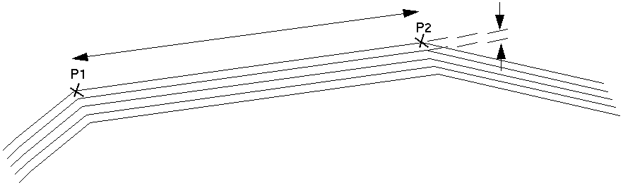
Distance from P1 to P2 is hundreds of units, for example 200 m. The distance between each of the 5 parallel lines is in single units, for example 5 m |
String geometry of this type is generally created by the Pit design module. The special feature here is that there are concentric strings, which have relatively large distances between consecutive points on the string and relatively short distances between the strings. | Create points at more regular intervals along the strings so that the ratio of distance between points on a string to the distance between the strings is not so extreme. In the case of pit design data, make the points at more regular intervals in the base string before commencing the pit design. |
|
||
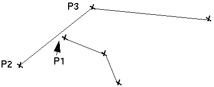
| Offset of Point P1 from the line going from P2 to P3 is very small - a few centimetres. | A point on one line comes very close to intersecting another line but does not actually meet it. | Move P1 to be either exactly on the line P2-P3 or move it further from the line P2-P3. |
|
||
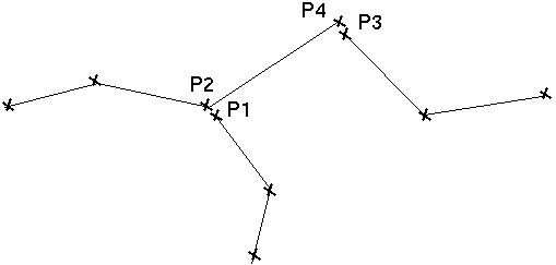
| Distance between P1 to P2 and P3 to P4 is very small - a few centimetres. | A point on one line comes very close to intersecting another line but does not actually meet it. |
Move the points so that they are exactly the same in X, Y, and Z, or move them further apart. |
|
|
These error messages appear only if some of the strings are being used as breaklines and the breakline intersection test is being performed. These messages indicate that an intersection has been found between two strings that are being used as breaklines. The string numbers and coordinates at which the intersections have been found are displayed so that you can determine the source of the problem and fix it. |
There are two ways to fix this problem.
|
|
|
These error messages indicate that a severe error condition has been found during the creation of the DTM. |
If you encounter any of these messages contact GEOVIA Support. |