


Drape an image over a DTM file
This function permits you to apply advanced rendering techniques to Digital Terrain Models and Solid Models by draping an image file over the surface or solid.
To run this function: Choose File > Images > Drape an image file over a DTM, or...
This drape technique is very useful when:
- An aerial photograph has been scanned and saved in a GIF file and you wish to drape it over a DTM of the surface to give a photo-realistic representation of the land surface. This technique requires you to digitise a number of control points, known as registration points, in the image and in the DTM.
- You want to display solid models of orebodies with a texture appropriate for rock type which it represents. In this case, you require a GIF file of a suitable texture which is then 'tiled' over the model.
This technique requires some effort to produce reasonable results as matching points in the image and the DTM must be selected with care otherwise the image will not match the DTM very well. The co-ordinates of the control points may be saved to a registration file (.rgf) to simplify future image rendering.
The image draping functionality supports with following image formats:
- Windows or OS/2 Bitmap File (*.BMP)
- Dr. Halo (*.CUT)
- Graphics Interchange Format (*.GIF)
- Windows Icon (*.ICO)
- Amiga IFF (*.IFF, *.LBM)
- JPEG Network Graphics (*.JNG)
- Independent JPEG Group (*.JPG)
- Commodore 64 Koala format (*.KOA)
- Multiple Network Graphics (*.MNG)
- Portable Bitmap (ASCII) (*.PBM)
- Portable Bitmap (BINARY) (*.PBM)
- Kodak PhotoCD (*.PCD)
- PCX bitmap format (*.PCX)
- Portable Graymap (ASCII) (*.PGM)
- Portable Graymap (BINARY) (*.PGM)
- Portable Network Graphics (*.PNG)
- Portable Pixelmap (ASCII) (*.PPM)
- Portable Pixelmap (BINARY) (*.PPM)
- Photoshop (*.PSD)
- Sun Rasterfile (*.RAS)
- Targa files (*.TGA)
- Tagged Image File Format (*.TIFF)
- Wireless Bitmap (*.WBMP)
- X11 Bitmap Format (*.XBM)
- X11 Pixmap Format (*.XPM)
Select the triangle of interest
Select a triangle on the trisolation to which the image file is to be applied to display the DRAPE IMAGE OVER A DTM or TRISOLATION form.
Registration file
The registration file stores the parameters used for registering an image file over a DTM so that the image can be made to match the DTM precisely. In addition to the name of the image file and the filter colour, the registration file records the image coordinates (X and Y pixel values) and the corresponding real world coordinates for each of the registration points. Once the registration file has been created, it can be used in drag and drop operations to recall the DTM file into the viewport with the image already draped over it.
If you are using either of the tiling options then any file name which you might enter into this field has no effect on the result.
A minimum of 3 registration points are required and a maximum of 100 can be used. As more registration points are used, the image will develop a progressively better match with the DTM. When graphically adding or editing the registration points, each point is marked with an "x" as well as a point number. The attributes of the markers and text can be altered by changed the rubberband colour and text attributes in the Default Preferences form in Surpac.
The registration file name is pre-loaded with the same name as the DTM file and it is recommended that this naming convention is adhered to as the drag and drop operation depends upon this naming link. If the registration file named does not exist then it is created and all the details are saved to it after the registration points have been defined.
You can elect to either register an image with new points, edit the existing registration points or tile an image. If you select to register with new points then they will effectively overwrite any previous data saved to the registration file for this image. If you select the register with existing points option then they are able to update the saved registration information either graphically or by keyboard. Registration files are commonly used to simplify the task of draping an image over a DTM as defining registration points repeatedly for the same image/DTM can be quite time consuming.
A DTM can also contain multiple objects within it and each of these objects can have a separate image draped over it. When the IMAGE DRAPE function is invoked you are asked to graphically select the object in the graphics window that you want to drape an image over. Any registration information that is entered subsequently will then be associated with this object within the DTM.
Once the registration information for an image has been defined and saved within a registration file, it can be easily dragged and dropped into the graphics workspace. Dragging and dropping a registration file will cause Surpac to load the DTM that is associated with registration file and then uses the registration file information to register or tile the image. Note that the process will fail if the software cannot find the DTM file that is associated with the registration file.
Image file
This is the image file which contains the image to be draped over the DTM. If the images are not already in one of the supported formats then they must be converted to a supported format for use by this function. There are a number of shareware products which perform this task. One of the better utilities is:
- For MS Windows, IrfanView is a small freeware (for non-commercial use) graphic viewer.
The size of the image files is a consideration when draping images over DTMs. Images resulting from aerial photography are commonly many megabytes in size. The smaller the size of the image file, the less memory will be used and the performance will consequently be faster.
Two strategies can be used to reduce the size of the image files to achieve optimum performance. These are:
- Crop the image so that only a rectangular region covering the area of interest is saved in a new file. This process is often sufficient to reduce the image size so that performance is acceptable.
- If cropping results in an unacceptably large image then you should attempt to scale the image. This process effectively discards pixels from the image (scaling by 50% discards every second pixel). Scaling with an appropriate value will often result in an image with an acceptable resolution and adequate performance.
If you plan to use this function to tile images of material textures over DTMs and trisolations you must first avail yourself of some GIF files of such textures. Many such images are available royalty free on the World Wide Web while others must be purchased.
Some Web sites where such images can be found, at the time this document was written, include:
- Texture Land
- CGSD Real Texture Library
- 3D Cafe's Tileable Texture and Graphics Database
- The Avalon Repository Texture Archive
- The UK VR-SIG 3D Object Archive
Image draping method
The image can be draped over the trisolation using one of two different methods, with each method having two variations. These methods are:
- Registering the image.
- Tiling the image.
This is where the image and the DTM over which it is to be draped are displayed side by side, in different viewports, and matching pairs of points are selected, using the mouse, to control the process of draping the image over the DTM.
This method is most suitable when the image is of an aerial photograph and the DTM is the land form at the time the photograph was taken.
The two variations for this method are:
register with new points
This method will use whatever registration points are displayed in the registration points scrolling region and will require more registration points to be defined. You may find that this method will be used a number of times with an image and DTM to progressively improve the match between the image and the DTM.
register with existing points
This method will only use the registration points displayed in the registration points scrolling region. If fewer than 3 registration points are present in the scrolling region when you press Apply, you will be required to define some more registration points. This method can also be used to graphically edit the positions of the existing registration points.
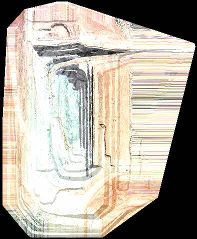
Above is an example of a DTM with an image draped over it.
This is where the image is given dimensions, in the real world X and Y directions, and the image is tiled over the selected trisolation in tiles of these dimensions.
This method is useful for applying images of different material textures to make solid models of orebodies, for example, appear more realistic. The best results will be achieved with images which have no obvious pattern especially when tiling over solid models as the image may be distorted considerably when folding underneath the solid model.
tiling
This tiling method simply places the image in tiles of the specified size over the trisolation.
mirror tiling
This tiling method creates a mirror image of every second tile, in both the X and Y directions.
Above is an example of a DTM with an image tiled over it.
Define registration points by
When using registration points, you always use the mouse to select the registration point locations in the image. To define the registration point coordinates in the DTM however you may choose from:
graphics
The mouse is used to select the location of the registration point on the DTM. When selecting this location, triangle Snap Mode is enabled so that the Z value of the position is precisely on the surface of the DTM. Use this method when only approximate locations for the registration points are known or when surface features, roadway intersections for example, are being used.
keyboard
The coordinates of the registration points are entered into a data entry form using the keyboard. This method is appropriate when the registration points are surveyed targets which are clearly identifiable.
Transmission colour
The textured image may be made transparent by specifying a transmission colour. This colour is allowed to shine through the textured object when another object falls behind it. Best results can be obtained by using a gray colour although any colour may be used for special effects. A bright transmission colour tends to generally darken the presentation of the texture map. The best results are generally obtained by using a medium gray colour.
Ambient colour
Some graphics adaptors, particularly when using the OpenGL display driver, may cause a dimming of the textured image. This can be countered by specifying an ambient colour that is reasonably light in colour. White is the brightest ambient colour that can be used and this will brighten the textured image considerably, although this may be at the expense of existing light sources. Light gray also works well for improving the image brightness. Strong colours will cause the textured image to become tinged with that colour.
Both the transmission colour and ambient colours have a tendency to stick to the trisolation to which they are applied. This has the effect that if either of these parameters are used and then the DRAW OBJECTS or DRAW DTM functions are subsequently used to redraw the trisolation without the textured image, these parameters will still influence the display of the trisolation.
To cancel the effect of the transmission colour and ambient colour as applied by the IMAGE DRAPE function, you can use either the CLEAR SCREEN or ERASE OBJECTS functions.
Image colour filter
The image colour filter works in a manner similar to colour filters in photography. By leaving the colour filter blank, the image is presented in the colours as defined in the image file.
To produce different effects, any colour may be used as a filter to give a tinge of the required colour to the image.
Define the tiling pattern size
X size, Y size
The size of tiles is only required if either of the tiling methods are being used. If so, then enter the size of the tiles, in real world units, for the X and Y directions.
Image and Real World coordinates for registration points
If an existing registration file is being used, all the saved parameters, including previously defined registration points are displayed here. There must be a minimum of 3 registration points to register the image to the DTM with the maximum number of registration points being 100. If insufficient registration points are displayed you will be required to define more before the image will be draped over the trisolation.
X image, Y image
These are the pixel coordinates for the locations of each of the registration points in the image.
X Data, Y Data, Z Data
These are the real world coordinates of the corresponding locations for registration points in the DTM.
Complete the DRAPE IMAGE OVER A DTM or TRISOLATION form and choose Apply to either drape the GIF image over the selected trisolation or to define registration points for controlling the image registration process.
If the image is being tiled over the trisolation, or if sufficient registration points have already been defined, no further input is required and the selected trisolation will be displayed with the image draped over it in the appropriate manner. If registration points have to defined, the graphics viewport is split vertically and the image is displayed in the right viewport and the trisolation is displayed in the lefthand viewport.
The registration points must now be defined by first selecting, using the mouse, a location in the image. To do this the prompt:
Digitise registration point # in viewport 2
is displayed. The "#" in the prompt is replaced by a number to indicate the number of the registration point which you are about to define. If you have defined sufficient registration points, there must be at least 3, you may press Escape to terminate the definition of registration points and to display the REVIEW REGISTRATION POINT COORDINATES form.
Locate the mouse over the required point in the image and press the mouse button to define the image coordinates for a new registration point. If you chose to define the registration points using the keyboard, the DEFINE COORDINATES FOR IMAGE REGISTRATION POINT form will be displayed. If you chose to define the registration points using graphics, the following prompt will be displayed:
Digitise registration point # on the DTM in viewport 1
Image coordinates for the registration point
X value, Y value
These are the coordinates of the point in the image selected by the mouse. These values cannot be changed on this form.
Define the real world coordinates for the registration point
X value, Y value, Z value
These are the real world coordinates of the registration point. Typically you will use coordinates of aerial targets which have been surveyed with some precision.
After digitising the location of the registration point in the DTM or entering the coordinates of the registration in the DEFINE COORDINATES FOR IMAGE REGISTRATION POINT form, you will be prompted to digitise another registration point. When sufficient registration points have been defined, press Escape to display the REVIEW REGISTRATION POINT COORDINATES form.
X Image, Y Image
These are the pixel coordinates for the locations of each of the registration points in the image.
X Data, Y Data, Z Data
These are the real world coordinates of the corresponding locations for registration points in the DTM.
Complete the REVIEW REGISTRATION POINT COORDINATES form and choose Apply to drape the image over the selected trisolation. Note that if you erase the trisolation or clear the screen, drawing the trisolation again will not render it with the image. To render the trisolation with the image again, you must use the IMAGE DRAPE function again.
Helpful Hints
Adjusting the view
When defining the registration points either in the image or in the DTM, it is generally necessary to adjust the view by either windowing in or out to find the best location for the registration point. By pressing the ASSIST key, generally F11 you can invoke the Viewer to adjust the view. On exiting from the Viewer you will be prompted to select the point of interest.
Resizing the viewports
The original viewport containing the selected trisolation is split vertically so the image and trisolation can be displayed side by side. You may find that the viewports are too small. It is possible to resize and move the active viewport while in the midst of a point digitise action if you find it necessary to alter the viewport size and/or location. If the two viewports overlap then the viewport in which the point must be digitised is brought to the front when necessary.
Finding the registration points
It is generally easier to locate the position of registration points in the DTM if the image has been rendered with a Light Source before starting the process of defining the registration points. This is because surface features are much more obvious when rendered with a light source and easier to relate to the image.
Memory usage
Image files, especially if they are large, can consume a considerable amount of memory. To estimate the memory requirements for displaying an image, use the following formula:
image memory usage = X pixels * Y Pixels * 3 bytes
Therefore, an image which is 1000 pixels square will require of the order of 2.5 Mb of memory.