


Create sections with multiple DTMs
You can use this function to extract cross sections from DTMs that have been created using the Create DTM function. The sections to be extracted are defined by using a cross-section axis and the spacing along the axis. The sections are taken along the axis length, at the interval defined by the spacing value.
To run this function: Choose Surfaces > DTM file functions > Create sections with multiple DTMs, or...
The coordinates that define the start and end positions for the axis are found in the axis record of the string file associated with the first DTM. If these coordinates are incorrect or do not exist, you can enter coordinates for the axis in the input fields.
You select DTMs on the Multiple DTM sections form in order of decreasing elevation. Sections can be taken as closed (using a pair of DTMs, a top and a bottom) or open (using a single DTM).
You can use a boundary string to constrain the sections that are produced. The boundary string can consist of multiple closed segments. For closed sections, the boundary string for the "top" DTM is used for both sections.
Fields on the Multiple DTM sections form
| Field | Description |
|---|---|
| DTM Specifications | |
| DTM Location | The name and location of the DTM you want to section. |
| Object ID | The object number of the DTM you want to section. |
| Object name | The object name of the DTM you want to section. |
| Trisolation ID | The trisolation number of the DTM you want to section. |
| Trisolation name | The trisolation name of the DTM you want to section. |
| Section type |
|
| Include |
|
| Boundary location | The name and location of the boundary string file. |
| ID | The ID number of the boundary string file. |
| String |
The string number of the boundary string, in the boundary string file.
Imagine that you are viewing a surface along the normal to the plane used during surface creation (that is, looking directly at the plane), the rules for clipping are:
|
| Define files to create | |
| Location | The name and location for the string file created. |
| Section |
|
| Section values | The range of values along the axis line at which the sections are created. |
| Define axis coordinates | |
| X | The X coordinates of the first and last points of the axis line. |
| Y |
The Y coordinates of the first and last points of the axis line. |
| Z |
The Z coordinates of the first and last points of the axis line.
|
| Section orientation is |
|
 Note: The boundary string can consist of any number of nested segments. The direction of these segments (clockwise or anticlockwise) is not important.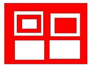
Output
A string file is created, which contains strings in different views depending on the orientation of the axis file. You can switch the coordinate data fields around using STRING MATHS to change them to plan view, or to transform them to real world coordinates if the axis was oblique.
When sectioning surfaces created on non-horizontal planes, the process is:
- The axis line is projected onto the plane.
- The surface and axis line are transformed so that the plane and axis line are horizontal.
- The section extraction process proceeds as for a horizontal plane surface.
Trouble Shooting
| Message | Description |
|---|---|
The selected were not created on the same plane.
|
The DTMs used must be created on the same plane. Choose different DTMs and recreate the DTMs on the same plane, or transform the data in one of the DTMs to match the plane of the other. |
You can use this function with clipped DTMs. However, this function might run more slowly if either of the clipped DTMs has a boundary that is concave in nature, for example:
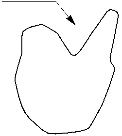
You will get a faster result if you use unclipped DTMs and nominate their boundary strings in this function.