


Create DTM from string file
You can use this function to create a surface from string data by forming a set of non-overlapping adjacent triangles between points in a string file.
To run this function: Choose Surfaces > DTM file functions > Create DTM from string file, or...
- In the Function Chooser, type CREATE DTM, and press ENTER.
- In the Layers pane, right-click and select Create DTM.
Fields on the Create a DTM from a string file form
| Field | Description |
|---|---|
| Define the string file | |
|
Location |
The input string file from which the DTM will be formed. The resultant DTM file will have the same Location Name as the string file that was used to create it, but have an extension of .dtm. |
|
Object ID |
The ID that is assigned to the surface. The ID must be a positive integer. |
| Object Name | The name that is assigned to the surface. The name can be blank or any character value; it will only be used in reports. |
| Projection plane | |
| Create on: |
The plane the DTM is created on. You can choose:
|
| After creating the surface, change the current plane to the best-fit plane |
|
| Define other parameters | |
|
Common point check distance |
The distance within which points are given the same X and Y coordinates. This is useful in avoiding problems that can occur when points are less than 0.005 from each other and some strings are being used as break lines. The maximum value for this field is 0.02. |
|
Strings to act as break lines |
If the surface is to accurately model the terrain, break line strings should be used. Break line strings are those strings which represent physical features that you can see in the real world. For example, the crest of a pit, or a fault in a geological model. If a string file has been formed correctly, then no break line strings will cross over other break line strings, unless the two strings cross at a common point. |
|
Any spot height strings |
|
|
Spot height string range |
The range of spot height strings. |
|
Perform break line test |
|
|
Interpolate additional points |
|
|
Point interpolation distance |
If Interpolate additional points is selected, the distance at which new points are created. |
| Define the boundary string to clip the DTM | |
|
Would you like to clip the DTM to a boundary after creation? |
The boundary string can consist of any number of nested segments. The direction of these segments (clockwise / anticlockwise) is not important. Imagine that you are viewing a surface along the normal to the plane used during surface creation (that is, looking directly at the plane), the rules for clipping are:
|
|
Boundary, String |
The boundary string file along with its ID and string number. The boundary string, and all of its segments, must be closed. |
|
Retain triangles inside boundary |
The portion of the surface to be retained is inside the specified boundary string. |
| Retain triangles outside boundary | The portion of the surface to be retained is outside the specified boundary string. |
 Note: This option is not available if the active plane is the XY plane.
Output
A .dtm file is created which can later be used by other commands or viewed in Graphics.
If you specified Strings to act as break lines, and crossing break lines are identified, each pair of break line segments is checked. The line pairs that cross are reported in a file with a Location and Id Number the same as the input string file but with a .not extension.
Troubleshooting
| Message | Description |
|---|---|
|
|
These error messages indicate that it was not possible to create the surface due to the geometric arrangement of strings, segments and points.
|
Error applying breakline to triangles. See warning messages for details.
|
A problem has occurred when adding a break line to the DTM surface. The warning messages will indicate the location of the problem. |
Errors
| Error | Description | Solution |
|---|---|---|
|
||
|
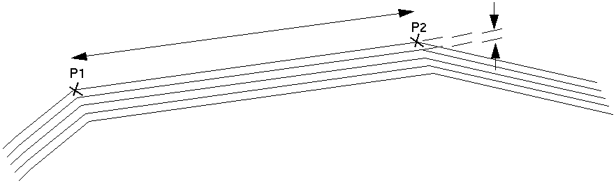
Distance from P1 to P2 is hundreds of units, for example 200 m. The distance between each of the 5 parallel lines is in single units, for example 5 m |
String geometry of this type is generally created by the Pit design module. The special feature here is that there are concentric strings that have relatively large distances between consecutive points on the string and relatively short distances between the strings. | Create points at more regular intervals along the strings so that the ratio of distance between points on a string to the distance between the strings is not so extreme. In the case of pit design data, make the points at more regular intervals in the base string before you start the pit design. |
|
||
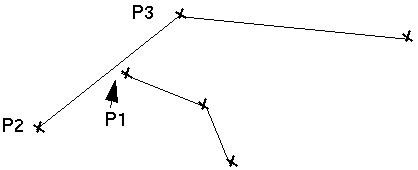
| Offset of Point P1 from line P2 to P3 is very small, of the order of centimetres. | A point on one line comes very close to intersecting another line but does not actually meet it. | Move P1 to be either exactly on the line P2-P3 or move it further from the line P2-P3. |
|
||
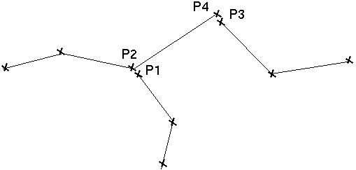
| Distance between P1 to P2 and P3 to P4 is very small, of the order of centimetres. | A point on one line comes very close to intersecting another line but does not actually meet it. |
Move the points so that they are exactly the same in X, Y, and Z, or move them further apart. |
|
Strings xxx and xxx intersect at xxxxxxN xxxxxE xxx Breakline intersections found ........ Cannot form the DTM String file failed the break line intersection test |
These error messages appear only if some of the strings are being used as break lines and the break line intersection test is being performed. These messages indicate that an intersection has been found between two strings that are being used as break lines. The string numbers and coordinates at which the intersections have been found are displayed so that you can determine the source of the problem and fix it. |
There are two ways to fix this problem. The first is to treat one of the strings as a spot height string. The second is to edit the string file in Graphics and move the locations of some of the points to prevent the intersections occurring. |
|
Incorrect number of triangles formed Triangle array is scrambled Fatal DTM error - Triangles are not adjacent Triangle stack underflow Triangle list overflow Searched full circle and can't find a neighbour |
These error messages indicate that a severe error condition has been found during the creation of the DTM. |
If you encounter any of these messages contact GEOVIA Support. |