


Block model isosurface
This function generates 3D triangulations of approximations to isosurfaces (that is surfaces with a constant attribute value) from data stored in the block model.
To run this function: Choose Block model > Block model > Export > Isosurfaces, or...
A range of values may be given in which case each value causes a separate object to be generated. Disconnected pieces of an isosurface for a given value are stored as separate trisolations within the object for that value.
It is possible to assign interpolated values of other attributes to the output vertices to enhance graphics visualisation.
As with all functions in Block Modelling, you may apply a simple or complex constraint to the model when generating the isosurface.
The 3DMs generated by this function would typically be used to enhance the visualisation of data; for example, the 2 gram cutoff surface without the chunky blocks produced by a normal block value constraint.
Generate isosurfaces to a FILE/LAYER
You have the option of saving the generated 3DMs to a file or to a graphics layer.
Location and Id Number
If saving to a file, enter the Location and Id Number of the file to create.
Purpose
If saving to a file, enter the purpose comment to save to the file.
Layer Name
If saving to a graphics layer, enter the name of the layer to use.
Rescale?
If saving to a graphics layer, you may select `Yes' to rescale the display to ensure that all of the generated isosurfaces are displayed.
Attribute
Enter the Attribute used to generate the isosurface. The value used for the isosurface is output as description field 1.
Note:Only real attributes are allowed.
Relation
The Relation is used to determine:
- The location of the triangles representing the isosurface. This is necessary when the block model contains values which result in a number of alternative locations for the isosurface being possible.
- Which way the triangles face. That is, if the triangle normal (the vector perpendicular to the triangle face) points towards the inside of the object or to the outside of the object.
To appreciate the effect of the choice of '<' as compared to '<=' or in a similar fashion how '>' compares to '>=' see the diagrams below.
To demonstrate the effect that these values have on the isosurface which is created a two dimensional analogy using contours is used.
If you choose '<' or '>=' the same contour (i.e. the isosurface) will be created and the contour (isosurface) will follow the path shown below.
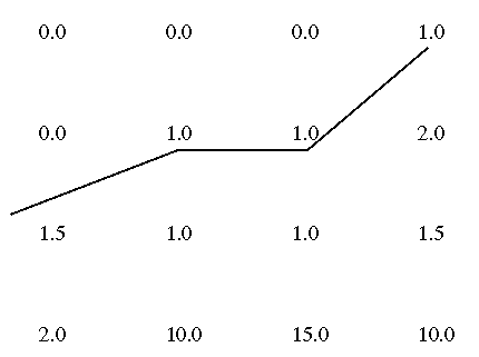
If you choose '>' compares to '<=' the same contour (i.e. the isosurface) will be created and the contour (isosurface) will follow the path shown below.
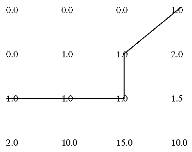
The result is influenced by the choice of '<' or '<=' as compared to '>' or '>=' by the determination of where the inside of the resultant object is considered to be:
- '<' or '<=' will cause the inside of the object to be on that side of the object where values less than the value of the isosurface exist.
- '>' or '>=' will cause the inside of the object to be on that side of the object where values greater than the value of the isosurface exist.
Values
Range of values for which isosurface triangulation objects will be created. Each value will result in a separate 3DM object.
Minimum/Maximum
In order to simplify the specification of values the minimum and maximum values for the selected attribute may be displayed by choosing the Calc Min/Max button.
Resolution
The resolution used will determine how finely the isosurface is followed. Using a resolution higher than the user block resolution will result in the resulting isosurface having a chunky staircase appearance. Using a lower resolution will result in fewer triangles in the 3DMs and shorter running time but produces a less precise result.
Algorithm
The algorithm used in partitioning the model is determined by this parameter. Using the CUBIC algorithm results in the model space being decomposed into cubes at the isosurface resolution and then triangulated. The TETRA algorithm uses tetrahedrons at the isosurface resolution. The CUBIC algorithm usually results in much fewer triangles being generated for a surface of similar quality and tends to run faster.
Constrain
This field is used to determine if the user wishes to constrain the volume of space for which the isosurface is calculated.
Note:The constraint will be reduced in resolution to the resolution of the isosurface.
Interpolated Attribute
Attribute to interpolate and output to the appropriate point description field. Description field 1 is always the attribute used for the isosurface.
Note:Only real attributes are allowed.
The interpolated attributes can be used to display an isosurface with the faces being coloured by an interpolated attribute via the DRAW SHELLS function.
Messages
Object n created for value v
An isosurface was generated for value v and stored in 3DM object n.
No isosurface generated for value v
Two blocks spanning the value v could not be found in the model and so no isosurface of value v passes through the model.
Result
A 3DM object is created for each value in the range given by values for which an isosurface passes through the model. These are either saved to the specified string file or drawn in the specified graphics layer.