


Underground traverse
With this function you can calculate and store new stations in the database. The backsight and setup stations, which must already be stored in the database, are entered and their coordinates are displayed for verification. The observation data which includes horizontal angles, vertical angles, slope distance and instrument and target heights are entered. The coordinates for the new station are then calculated, displayed and stored in the database.
To run this function: Choose Survey > Underground surveys > Underground traverse, or...
level_area for new stations
All stations in a survey database are grouped by the level_area field so that it easy to reference stations in the same level/area of the mine. You must enter the level/area into which the new station/s being created by this function will be assigned.
Details for Traverse Report
Enter the names of the persons who will enter and check the calculations. Also enter the field book which contains the original field observations and the page reference in that field book. This information is only used for the formatted traverse report created by this function.
Define the Traverse Report File
Enter the name of the report file to be created in the Location field. Choose the report type using the Output report file format field.
Complete the Traverse Report Details form and choose Apply to display the Underground Station Traversing form.
Backsight
Enter the name of the station which will be used as the backsight station for this section of the traverse. After entering the station name and pressing return, the coordinates of the station will be obtained from the database and displayed for reference. Note: the z floor value of the station is only displayed if the backsight is an underground station.
Setup and Height
Enter the name of the station which will be used as the setup station for this section of the traverse. After entering the station name and pressing return, the coordinates of the station will be obtained from the database and displayed for reference. Note: the z floor value of the station is only displayed if the setup is an underground station.
You must also enter the height of the instrument axis above the station. The convention used is that distances measured from the station up to the axis are positive while distances measured from the station down to the axis are negative. Therefore, if the station is in the back of the drive, the instrument height will be negative.
After entry of the setup and backsight stations the bearing and distance from the setup station to the backsight station are displayed for reference.
Note:If the station_fr field of the setup station matches the name of the backsight station then the stored bearing from the database (in preference to the calculated bearing between the two stations) will be used to calculate the coordinates of the foresight station.
This is particularly relevant when lines of sight between stations are very short as is often the case in underground mines.
Foresight
Enter the name of the station which will be used as the foresight station for this section of the traverse. Typically the foresight station should not exist in the database unless a resurvey is being conducted. After entering the station name and pressing return, the database is checked and if the station exists, the coordinates of the station will be obtained from the database and displayed for reference.
level_area
All stations in a survey database are grouped by the level_area field so that it easy to reference stations in the same level/area of the mine. You must enter the level/area into which the new station/s being created by this function will be assigned. This is the same value that was entered on the Traverse Report Details form. The input field is included here so that you can easily change the level/area as the traverse progresses.
Instrument used
Enter the instrument (as defined in the station errors table) used for the calculations. For explanatory information on the station errors table see here. This pick-list will be populated with the instruments from the station errors table. This field will only be selectable if BOTH of the following hold:
- A station errors table exists in the survey database
- Multiple instruments have been defined in the station errors table (ie there is a choice of instruments)
Check distance to backsight & Check backsight height
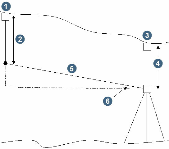
A problem unique to surveying in underground mines is the possible confusion over the station used as a backsight or setup. This occurs due to the poor working conditions found underground and the proximity of some survey stations to other survey stations. To counter this, and to provide a mechanism for preventing gross errors in surveys due to use of an incorrect backsight station, provision is made for (optionally) entering further information to allow checks to be performed to ensure that the correct setup and backsight stations are being used. The nature of these checks is illustrated in the following diagram:
|
1. backsight station 2. backsight target height 3. setup station 4. setup height 5. slope distance 6. mean reverse angle |
The convention used for the backsight target height and setup height is as follows: distances measured from the station up are positive while distances measured from the station down are negative. Therefore, if the station is in the back of the drive, the height will be negative.
The checks are:
(i) Backsight distance check To perform this check you must enter vertical angles and slope distances from the setup station to the backsight. This provides a check by comparing the measured horizontal distance (= slope distance * cos(mean reverse angle)) with the known horizontal distance between the two stations.
(ii) Backsight height check To perform this check you must enter the values for check (i) and also enter the backsight target height and the setup station height. This provides a check by comparing a calculated backsight station elevation with the known backsight station elevation. The calculated backsight station elevation is produced as follows:
calculated backsight elevation = (known setup station elevation) + (setup station height) + (slope distance * sin(mean reverse angle)) - (backsight target height)
Note: No adjustments to the setup station or backsight station coordinates are made when using these checks.
Select the Check distance to backsight tickbox to check the distance from the setup station to the backsight station. This will require you to enter the observed vertical angles and slope distance from the setup station to the backsight station.
If you have selected the Check distance to backsight option you can also select the Check backsight height option. This will require you to also enter the backsight target height. (Note that you will also need to enter the setup station height, at the top of the form, see Setup and Height above).
Vertical angles from Setup to Backsight
Enter each angle observation and then choose the Mean Reverse Angle buttons to calculate and display the individual angles of elevation or depression for the reverse vertical angles and to also calculate and display the mean reverse vertical angles.
Slope Distance
Enter the observed slope distance from the setup station to the backsight station.
Backsight target height
Enter the distance from the backsight station to the backsight target. The convention used is that distances measured from the station up to the target are positive while distances measured from the station down to the target are negative. Therefore, if the station is in the back of the drive, the backsight target height will be negative.
After entering the reverse vertical angles and the slope distance (and the backsight target height and setup station height if a backsight height check is also required), choose the Calculate backsight checks button to calculate and display the horizontal distance from the setup station to the backsight station and the error as compared to the known distance between the setup station and the backsight station (and to calculate and display the calculated backsight station elevation and the error as compared to the known backsight station elevation, if a backsight height check was also requested).
If the error(s) is/are significant you should check that the correct backsight and setup stations are being used before proceeding with the traverse.
New Floor to Setup Height
Height
It is common to check the floor elevation at the setup station as new surveys are conducted from it by measuring a height from the floor to the instrument axis at the setup station when a new survey is carried out. The purpose is to update the floor level of the setup station in the database.
Enter "Y" to alter the floor elevation of the setup station. The input field for the new floor to setup height must be entered into the Height input field. If you choose this option, the database entry for the setup station will be altered, after confirmation on the Review Underground Station Co-ordinates form. The Review Underground Station Co-ordinates form will be displayed after choosing Apply from the UNDERGROUND STATION TRAVERSING form.
Enter "N" to prevent the floor elevation of the setup station from being modified.
Horizontal angle observations
Two different methods of entering horizontal angle observations are provided. Depending on the method chosen, the required input fields will be made visible for data entry while the input fields for the other method will be blanked out. Choose the required method of horizontal angles as either:
- reiteration
Use this method of observing horizontal angles when using a theodolite which does not permit clamping of the horizontal circle to the upper plate of the theodolite. An example of this is the WILD T2 theodolite.
- repetition
Use this method of observing horizontal angles when using a theodolite which permits both the upper and lower plates of the theodolite to be clamped. An example of this is the WILD T16 theodolite.
Reiteration Angles
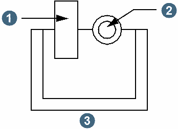
This method of horizontal angle observations requires that matching pairs of angles to both the backsight and foresight stations be recorded and entered into the input fields on the form. Typically a round of angles consists of face left angles to both the backsight and foresight stations and face right angles to the backsight and foresight stations.
|
1. vertical circle 2. telescope 3. face left |
If multiple rounds of angles are observed then the horizontal circle is often rotated prior to reading each new round to minimise errors due to horizontal circle eccentricity and graduation errors.
For efficient data entry the field book recording sheet for this method should look something like the table below:
| Face | Backsight | Foresight | Angle |
| Left | |||
| Right | |||
| Left | |||
| Right |
Each of the turned angles is calculated by the program so there is no need to enter each of the turned angles even though they will probably have been calculated by the surveyor in the field.
Repetition Angles
This method of horizontal angle observations involves the accumulation of repeated observations of the angle between the backsight and foresight stations from the setup station and then finally dividing the accumulated angle by the number of times it has been measured. This requires the use of a theodolite where the lower plate (the horizontal circle) can be clamped to the upper plate so that successive foresight angles can be established as the angle for the next backsight observation thus enabling the accumulation of the angle for each new measurement.
The sequence of measurements is typically:
- Set zero to the backsight station
- Measure the face left angle to the foresight station
- Clamp the horizontal circle
- Change face, sight to the backsight station and release the clamp on the horizontal circle
- Measure the face right angle to the foresight station (steps 3, 4 and 5 are repeated as often as required)
For efficient data entry the field book recording sheet for this method should look something like the table below:
| Station | Observed | Angle |
| Backsight | ||
| Foresight (face left) | ||
| Foresight (face right) | ||
| Foresight (face left) | ||
| Foresight (face right) |
Each of the turned angles is calculated by the program so there is no need to enter each of the turned angles even though they will probably have been calculated by the surveyor in the field.
Enter the observed angles into the appropriate input field and then choose the Mean Repetition Angles button or the Mean Reiteration Angles button to calculate and display each of the observed angles. This will also result in the mean horizontal angle being displayed.
After reviewing the calculated angles, use the outer scroll bar to scroll down to the data entry region for the vertical angles and slope distance.
Vertical angle observations to
Choose the type of vertical angle observations which you wish to enter by using the selection browser to select either:
- 1 target
This method requires that the observation and entry of vertical angles, slope distances and heights of target from floor and back to be entered. This is the most commonly used method. Choosing 1 target will ensure that input fields relating to target 2 will be made invisible to avoid confusion.
After choosing 1 target, enter the forward vertical angles measured from the setup station to target 1 at the foresight station. Angles must be entered into the Target 1 vertical angles scrolling region. Enter each angle observation and then choose the Mean Forward Angle button to calculate and display the individual angles of elevation or depression and to also calculate and display the mean forward vertical angle.
- 2 targets
This method is used when it is necessary to obtain a more precise measure of the elevation for the foresight station. It involves the observation of vertical angles, slope distances and heights of target from the floor and back to two targets at the foresight station. Each target is suspended at different heights below the foresight station.
The net effect is that two elevations are derived for the foresight station with these elevations being averaged prior to storing in the database.
This choice permits you to enter vertical angles, slope distances and target heights for both target 1 and for target 2. Angles must be entered into the Target 1 vertical angles scrolling region and into the Target 2 vertical angles scrolling region.
Enter each angle observation and then choose the Mean Forward Angle buttons below each scrolling region to calculate and display the individual angles of elevation or depression to each of the 2 targets.
Heights to Target 1, Station to target and Floor to target
You must also enter the heights from the foresight station to target 1 and from the floor to target 1. The convention used is that distances measured from the station up to the target are positive while distances measured from the station down to the target are negative.
Heights to Target 2, Station to target and Floor to target
These inputs are only required if you have chosen to observe to 2 targets. If this is so then you must enter the heights from the foresight station to target 2 and from the floor to target 2. The convention used is that distances measured from the station up to the target are positive while distances measured from the station down to the target are negative.
Target 1 Slope Distances, Whole and Part
Traditional means of surveying in underground mines require the use of a steel tape to measure distances. For each distance measured this typically involves two tape readings. These being the Whole measurement (the far end of the tape) and the Part measurement (the near end of the tape).
Enter as many Whole and Part measurements to target 1 as required and choose the Mean Horizontal Distance button to calculate and display each of the individual measured distances to target 1 and also to calculate and display the mean horizontal distance to target 1.
Target 2 Slope Distances, Whole and Part
Enter as many Whole and Part measurements to target 2 as required and choose the Mean Horizontal Distance button to calculate and display each of the individual measured distances to target 2 and also to calculate and display the mean horizontal distance to target 2.
Reverse heighting
Calculate using reverse heights and distances
It is common practice to improve the accuracy of the elevations of the new station by measuring reverse vertical angles and slope distances from the foresight station back o the setup station.
If you use this method then enter "Y" to permit entry of the reverse angles and distances in the appropriate data entry fields. If you do not use this method enter "N" and proceed to calculate the new co-ordinates for the station.
Reverse vertical angle observations to
As with the forward vertical angles and slope distances, it is possible to measure the reverse vertical angles and slope distances to 2 different targets suspended at different heights below the station. This practice is usually employed on steep lines of site to enhance the accuracy of the elevations.
Select either:
- 1 target
This method requires that the observation and entry of vertical angles, slope distances and height of target from the back to be entered. This is the most commonly used method. Choosing 1 target will ensure that input fields relating to target 2 will be made invisible to avoid confusion.
After choosing 1 target, enter the forward vertical angles measured from the foresight station back to target 1 at the setup station. Angles must be entered into the Target 1 vertical angles scrolling region. Enter each angle observation and then choose the Mean Forward Angle button to calculate and display the individual angles of elevation or depression and to also calculate and display the mean reverse vertical angle.
- 2 targets
This method is used when it is necessary to obtain a more precise measure of the elevation for the foresight station. It involves the observation of vertical angles, slope distances and heights of targets from the back to two targets at the setup station. Each target is suspended at different heights below the setup station.
The net effect is that two elevations are derived for the foresight station with these elevations being meaned prior to storing in the database.
This choice permits you to enter vertical angles, slope distances and target heights for both target 1 and for target 2. Angles must be entered into the Target 1 vertical angles scrolling region and into the Target 2 vertical angles scrolling region.
Enter each angle observation and then choose the Mean Forward Angle buttons below each scrolling region to calculate and display the individual angles of elevation or depression to each of the 2 targets.
Station to instrument
Station to target 1
Station to target 2
You must also enter the heights from the station where the instrument is situated (the new foresight station in fact), to the instrument axis, and the heights from the station where the target/s are situated (the original setup station) to the target axes.
As with other heights, the convention used is that distances measured from the station up to the axis/target are positive while distances measured from the station down to the axis/target are negative.
Target 1 Slope Distances, Whole and Part
Enter the reverse slope distance observations from the foresight station back to target 1 at the setup station. Traditional means of surveying in underground mines require the use of a steel tape to measure distances. For each distance measured this typically involves two tape readings. These being the Whole measurement (the far end of the tape) and the Part measurement (the near end of the tape).
Enter as many Whole and Part measurements to target 1 as required and choose the Mean Horizontal Distance button to calculate and display each of the individual measured distances to target 1 and also to calculate and display the mean horizontal distance to target 1.
Target 2 Slope Distances, Whole and Part
Enter the reverse slope distance observations from the foresight station back to target 2 at the setup station. Enter as many Whole and Part measurements to target 2 as required and choose the Mean Horizontal Distance button to calculate and display each of the individual measured distances to target 2 and also to calculate and display the mean horizontal distance to target 2.
After all of the observation data has been entered, choose the Calculate Co-ordinates button to calculate the coordinates of the foresight station. The coordinates of the setup station will be displayed in the display fields at the top of the form for the foresight station. When you are satisfied that the entered observations and resulting coordinates are acceptable, choose Apply to process the data on the form.
Using an Underground Survey Database
Surveying in underground mines presents some unique problems caused by the frequent occurrence of very short lines of sight. The bearings which are subsequently calculated using the known station coordinates on these very short lines are likely to deviate significantly from the bearings obtained by successively adding the horizontal angles to the bearing from the setup station to the backsight station. To resolve this problem, the underground survey database has a field `rev_brng' in which the carried bearing is stored. Any survey function which accepts input of survey observations to calculate the coordinates of new points will use this stored bearing, if appropriate, to calculate the coordinates of the new points.
With respect to underground survey databases, connections between stations are defined by the contents of the `station_fr' field for each station in the database.
The following logic is employed by the calculation module to obtain the bearing from the setup station to the backsight station.
- If no connection exists between the setup and backsight stations then a form is displayed advising that the backsight/setup station pairing may be unsuitable.
The reason why the pairing may be unsuitable is that, due to a mistake in recording the backsight or setup station names, there may be no line of sight between the two stations due to intervening solid rock.
If this situation occurs the INCONSISTENT BACKSIGHT/SETUP STATION COMBINATION form is displayed.
Choose Apply to obtain the bearing from the setup station to the backsight by calculating it from the known coordinates of the stations.
Choose Cancel to abort the coordinate calculation process completely. You would make this choice if you wish to check on the backsight and setup station names before proceeding.
- If a connection between the setup and backsight stations exists, then the stored bearing from the database and the calculated bearing obtained by using the known coordinates of the two stations are compared.
If the difference between the bearings is less than 2 minutes then the calculation of coordinates will continue and the stored bearing will be used.
If the bearings differ by greater than 2 minutes then the INCONSISTENT DATABASE REVERSE BEARING VALUE form is displayed.
The stored and calculated bearings between the setup and backsight stations are displayed. You must choose one of three possible actions by choosing the appropriate button to determine how you should proceed from this point.
Choose Use stored bearing to proceed with coordinate calculations using the bearing obtained from the database as the bearing from the setup station to the backsight station.
Using underground type stations
See here for notes on the use of underground type stations, in particular in relation to the use of calculated versus stored bearings for underground stations.
Use of the station errors table
If a station errors table exists in the survey database, information regarding the order of the new station may be displayed. For explanatory information on the station errors table see here. When calculating the vertical angle standard deviation and number of vertical angle observations to pass to the station errors table to calculate the new station order, Surpac uses the following approach. Vertical angles can be entered to 1 target or 2 targets, and reverse vertical angles can also be entered to 1 target or 2 targets. Surpac calculates individual standard deviation values, and numbers of observations (up to 4) for each of these groups of vertical angle measurements. Surpac then uses the largest of these individual standard deviations (and the corresponding number of observations value) to send to the station errors table. A similar approach is used when calculating the slope distance standard deviation and number of slope distance observations to pass to the station errors table. That is, up to 4 individual standard deviations for the forward and/or reverse slope distances are calculated, and the largest of these individual standard deviations (and the corresponding number of observations value) is used.
If you have entered a single horizontal angle, a single vertical angle and a single slope distance then see here for more details of the information that is displayed by the station errors table. If you have entered multiple angles and/or slope distances then see here for more details of the information that is displayed by the station errors table.
Note: The Review Underground Station Co-ordinates form will be displayed to confirm changes to the setup station if you have chosen to recalculate the floor elevation of the setup station by measuring a new floor to setup height.
The Review Underground Station Co-ordinates form is is displayed to permit final review of the data for the foresight station before it is committed to the database.
You may take this opportunity to enter or alter any of the data for optional fields which may exist in the database.
Complete the Review Underground Station Co-ordinates form and choose Apply to commit the foresight station details to the database. After successfully saving the foresight station to the database, the UNDERGROUND STATION TRAVERSING form will be displayed to permit the continuation of the traverse. This form will continue to be displayed to accept further observations until you choose Cancel.
Choose Cancel to discard the observations and calculations for the foresight station and to complete the UNDERGROUND TRAVERSE function.
The observation data and a summary of the calculations can be saved in a variety of formats for reporting and for future audit purposes. An example of a note file produced by this function is shown below.
Note:This function will use the scale factor defined by the "scale factor" option of the defaults file when calculating the horizontal distance from the observed slope distance and vertical angles. This permits you to adopt a regional scale factor for the mine area if you find it necessary to make adjustments for the curvature of the Earth.
				                    TRAVERSE CALCULATION REPORT
				Calculated :  GJT
				Checked    :  TRS
				Fieldbook  :  45
				Page Ref   :23
				               Station         Y         X        Z    Floor
				Backsight      25L7     4944.830  2067.100  256.180  252.180
				Setup station  25L9     4944.790  2081.290  256.180  250.510
				Foresight      25L12    4962.644  2063.746  254.187  250.202
				FORESIGHT STATION INSERTED
				SETUP TO BACKSIGHT CHECKS:
				Reverse Vertical Angles  Observed   Angle
				1                         90.0100  -.0100
				2                        269.5912  -.0048
				Mean angle                         -.0054
				Distance Check
				Slope Distance       :    14.2100           Horizontal Distance  :    14.2100
				                                            Error                : >>>      .0200 <<<

				HEIGHT CHECK
				Setup height                                :     -4.050
				Backsight elevation                         :    256.180
				Check elevation      :    256.226           Error                : >>>      .0460 <<<

				SETUP STATION        Floor Level Updated.
				                     Floor to Setup height  :      1.760

				Inst:-               25L9
				Y = 4944.790         X =    2081.290        Z =    250.180       Floor = 250.510

				Scale Factor         : 1.0000000000

				Reverse Bearing      : 270.0941             Reverse Distance     : 14.1900
				Forward Bearing      : 315.3004             Forward Distance     : 25.0310
				HORIZONTAL ANGLES - REITERATION METHOD.
				            Backsight  Foresight    Angle
				1              0.0000    45.2030  45.2030
				2            180.0000   225.2020  45.2020
				3             90.0000   135.2020  45.2020
				4            270.0000   315.2020  45.2020
				Mean angle                        45.2022
				TARGET 1 OBSERVATIONS
				Forward Vertical Angles  Observed   Angle
				1                         90.2000  -.2000
				2                        269.2000  -.4000
				3                         90.2000  -.2000
				4                        269.2000  -.4000
				Mean angle                         -.3000
				TAPE DISTANCE
				                      Whole  Part  Distance
				1                    25.132  .100    25.032
				Mean tape distance                   25.032
				Horizontal distance                  25.031
				Back to Target :  -4.050      Floor to Target :   1.000
				Back to Setup  :  -4.050
				REVERSE TARGET 1 OBSERVATIONS
				Forward Vertical Angles  Observed   Angle
				1                         90.0100  -.0100
				2                        269.5912  -.0048
				Mean angle                         -.0054
				TAPE DISTANCE
				                     Whole   Part  Distance
				1                    25.132  0.100  25.0320
				Mean tape distance                  25.0320
				Horizontal distance                 25.0310
				Back to Target :  -2.225
				Back to Setup  :  -4.00
				level_area: 25
				Other Fields
				date_stamp     2004-08-17 10:37:05
				station_type                    UG
				station_fr                    25L9
				elev_dif                    20.218
				rev_brng                  135.3004
				surveyor                       GJT
				survey_date    2004-08-16 11:18:33
				checked_by                     TRS
				field_book                      45
				pages                           23
				station_order