


Profile Survey
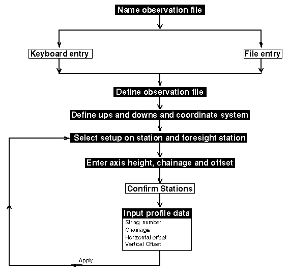
Profile surveys are useful for producing section profiles of underground drives, (both narrow and wide stopes). This function enables you to input survey field data, of horizontal and vertical offsets at a chainage, and the subsequent reduction will form a section profile at that chainage. This forms a string file, which can be recalled and used in the GRAPHICS module for further processing and viewing.
To run this function: Choose Survey > Underground surveys > Profile survey, or...
From the Survey database menu, select Underground surveys, then Profile survey to invoke the function.
Database Name
The current database name is displayed and cannot be changed in this form.
Define the Observation File
Enter the Location name and ID number of the observation file.
Data entry from
Describe the process of data entry. If the entry is keyboard input from a survey field book, then enter `K'eyboard. If the entry is from a file, then enter `F'ile. Usually file entry will come after data has been entered by keyboard, editing has occurred, and re-entry is required for further processing. The default value is `K'eyboard.
Complete the UNDERGROUND STOPE OR DRIVE PICK UPS form and choose Apply. If the observation file already exists the VERIFY CREATION OF A FILE form is displayed.
If you entered `F' to indicate the data entry is from a file, the UNDERGROUND STOPE OR DRIVE PICK UPS form is displayed, if you entered `K' skip this form.
Database Name
The current database name is displayed and cannot be changed in this form.
Define file to be recalled
Enter the Location and ID number of the file that contains the data. Complete the form and choose Apply to continue.
Database Name
This is the name of the current database and cannot be changed in this form.
Define the Observation File Header Details
Enter the Purpose of Job in a manner that is beneficial to you when reviewing the report file. Enter the name of the persons involved in the survey (Surveyor), the Date, the Fieldbook name or number and the relevant Pages. Blank fields are accepted, as you are not required to define the file details.
Database Name
This is the name of the current database and cannot be changed in this form.
Ups and Downs
Describe the measurement method of your ups and downs as either VERTICAL ups or downs from the tape or line of sight, or PERPENDICULAR ups and downs to the slope of the tape or line of sight. The default value is VERTICAL.
Perpendicular ups and downs are useful when surveying in a very steep raise as it is often easier to measure ups and downs perpendicular to tape.
It is important that you enter a value which agrees with the method of measuring the ups and downs otherwise the results are likely to be incorrect.
Coords to save
Valid entries are:
-
SECTION, if you wish to have the section profile coordinates determined
with regard to the section itself. If you choose section coordinates,
the resultant string file fields contain:
y elevation x offset z chainage D1 Northing D2 Easting -
WORLD, if you wish to have real world coordinates saved. If you choose
world coordinates the resultant string file fields contain:
y Northing x Easting z elevation D1 chainage D2 offset
The default value is SECTION.
Complete the UNDERGROUND STOPE OR DRIVES PICK UPS form and choose Apply to display the UNDERGROUND PICK UPS - PROFILE SURVEYS form.
Database Name
This is the name of the current database and cannot be changed in this form.
Set Up On Station
Station Id
Enter the station name of the occupied station.
Station to Instrument Axis
Enter the distance from the station to the instrument axis. Remember, measurements from the back (roof) to the instrument are -ve, and from the instrument to the floor are +ve.
Chainage, Offset
Enter the Chainage value and the Offset of the chain to the instrument station.
Foresight Station
Station Id
Enter the station name of the foresight station.
Foresight to Target Axis
Enter the distance from the station to the target axis. Remember, measurements from the back (roof) to the instrument are -ve, and from the instrument to the floor are +ve.
Chainage, Offset
Enter the Chainage value and the Offset of the chain to the target station.
Complete the UNDERGROUND PICK UPS - PROFILE SURVEYS form and choose Apply. If you enter a station name that is not found in the database, then a message will appear in the message window and the UNDERGROUND PICK UPS - PROFILE SURVEYS form remains to re-enter the setup and foresight stations. If the setup and foresight stations are not connected by virtue of the station_fr field of the foresight station, a message is displayed in the message window and a CONFIRM FURTHER PROCESSING form is displayed.
Choose Apply to accept the setup and foresight stations as entered and display the CONFIRM STATIONS form.
Database Name
This is the name of the current database and cannot be changed in this form.
Set Up On Station
The occupied station name is displayed together with its coordinates gathered from the database.
Foresight Station
The foresight station name is displayed together with its coordinates gathered from the database.
Calculated Distance
A distance check is carried out between the calculated distance from the station coordinates, and the chained distance laid out
(with consideration to the offset distances and the slope of the chain).
Choose Cancel to return to previous form for alterations.
Choose Apply to confirm the stations, and display the UNDERGROUND SECTION PROFILE SURVEY form.
Database Name
This is the name of the current database and cannot be changed in this form.
String No, Chainage, Horiz. Offset, Vert. Offset
Each profile should have a unique string number. The chainage input is the chainage for that survey profile. Enter the horizontal offsets left (-ve) and right (+ve) of the chain. Also enter the vertical offset at each horizontal offset position.
The profile is automatically closed from the last point on a string to the first point of the string.
The following is an example of a profile survey input table.
| Point No. | String No. | Chainage | Horiz Offset | Vert Offset |
| 1 | 1 | 10.0 | 5.0 | 0.0 |
| 2 | 1 | 10.0 | 5.0 | 2.5 |
| 3 | 1 | 10.0 | -5.0 | 0.0 |
| 4 | 1 | 10.0 | -5.0 | 3.0 |
| 5 | 2 | 20.0 | 6.0 | 0.1 |
| 6 | 2 | 20.0 | 6.0 | 2.4 |
| 7 | 2 | 20.0 | -4.6 | 0.0 |
| 2 | 20.0 | -4.6 | 3.2 |
When you have finished entering data choose Apply, and the UNDERGROUND PICK UPS - PROFILE SURVEYS form is displayed for further chainage and offset entries from a new station, choose Cancel to exit to the SURVEYING menu.
Using an Underground Survey Database
Surveying in underground mines presents some unique problems caused by the frequent occurrence of very short lines of sight. The bearings which are subsequently calculated using the known station coordinates on these very short lines are likely to deviate significantly from the bearings obtained by successively adding the horizontal angles to the bearing from the setup station to the backsight station. To resolve this problem, the underground survey database has a field `rev_brng' in which the carried bearing is stored. Any survey function which accepts input of survey observations to calculate the coordinates of new points will use this stored bearing, if appropriate, to calculate the coordinates of the new points.
Note:The following discussion only has relevance if you are using an underground database. If you are using a surface database then bearings are ALWAYS calculated using the known station coordinates.
With respect to underground survey databases, connections between stations are defined by the contents of the `station_fr' field for each station in the database.
The following logic is employed by the calculation module to obtain the bearing from the setup station to the backsight station.
-
If no connection exists between the setup and backsight stations then
a form is displayed advising that the backsight/setup station pairing
may be unsuitable. The reason why the pairing may be unsuitable is that,
due to a mistake in recording the backsight or setup station names, there
may be no line of sight between the two stations due to intervening solid
rock. If this situation occurs the INCONSISTENT BACKSIGHT/SETUP
STATION COMBINATION form is displayed.
Choose Apply to obtain the bearing from the setup station to the backsight by calculating it from the known coordinates of the stations.
Choose Cancel to abort the coordinate calculation process completely. You would make this choice if you wish to check on the backsight and setup station names before proceeding.
-
If a connection between the setup and backsight stations exists, then
the stored bearing from the database and the calculated bearing obtained
by using the known coordinates of the two stations are compared.
If the difference between the bearings is less than 2 minutes then the calculation of coordinates will continue and the stored bearing will be used.
If the bearings differ by greater than 2 minutes then the INCONSISTENT DATABASE REVERSE BEARING VALUE form is displayed.
The stored and calculated bearings between the setup and backsight stations are displayed. You must choose one of three possible actions by choosing the appropriate button to determine how you should proceed from this point.
Choose Use stored bearing to proceed with coordinate calculations using the bearing obtained from the database as the bearing from the setup station to the backsight station.
Choose Use Calculated bearing to proceed with coordinate calculations using the bearing obtained from the known coordinates of the setup station and the backsight station.
Choose Cancel to abort the coordinate calculation process completely. You would make this choice if you wish to check on the backsight and setup station names before proceeding.
If the point being surveyed is a new survey station, the reverse bearing from the new survey station to the station from which it was surveyed is stored in the rev_brg field.
Messages
'n' points written to file filename#.str
Result
The function underground profile survey has formed a `.str' file containing the survey data entered. A `.dat' file has also been formed containing all the data input, and this one is preferred if wanting a hardcopy.
If the data has been entered incorrectly, the `.dat' file may be edited using a text editor. This avoids having to re-enter the data.