


3D Transformation of string file
You can use this function to perform a 3D coordinate transformation on a range of string files. This function is often used to transform a string file so that you can obtain a hard copy plot, using the PLOTTING module, of the data in a 3D orthographic projection. The 3D transformation involves translation, rotation and scaling of the data.
To run this function: Choose File tools > Transformations > 3D Transformation of string file, or...
Two spatial locations are important to the 3D TRANSFORMATION, the eye point and the view point. The view point, or transformation centre, is the point about which rotations are performed. The coordinates of the view point are important. If the coordinates of the view point are close to the centre of the string data the transformation rotation will effectively spin the data on an axis. If the view point is a distance from the data of the string files it will instead revolve the data around the view point.
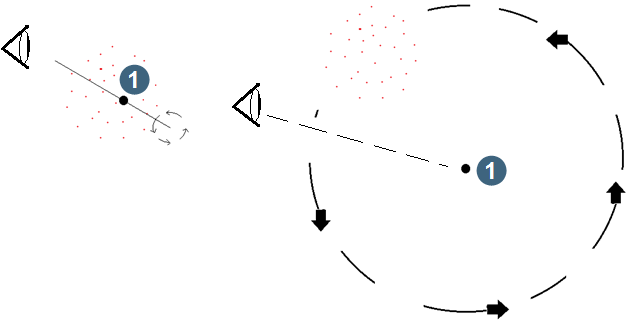
|
| 1. view point |
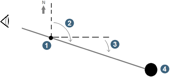
The eye point is any point along the line that has the bearing and dip for the transformation towards the view point. The dip and bearing towards the view point are important, but the coordinates of the eye point are not.
|
|
1. eye point 2. bearing = 3. dip = 4. view point |
The transformation is defined by entering:
- the direction from the eye point to the view point as a bearing and dip.
- the transformation centre point about which any necessary rotations are performed.
- scaling values for the X, Y and Z directions.
It is quite common to exaggerate the scale in the Z direction to produce a more visually impressive plot. The amount of exaggeration required is data dependant.
Because this function is used primarily to prepare data for plotting, it includes an option to Create box string file for grid. When selected, this creates a second string file that contains strings that define a 3D box containing the data. This allows you to orient the data more easily on a hardcopy plot.
The string file created by Create box string file for grid is created in the same coordinate space as the transformed strings. This makes it simple to plot the box strings and the transformed strings together on the one map. The box string file contains 12 strings which you can plot as required to make the final map easier to interpret.
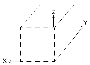
Strings 1 and 4, 5 and 8, and 9 and 12 all travel in the original coordinate system in the X, Y and Z directions respectively. You can use these strings to annotate the plot with the original real world values.
Fields on the 3D transform form
| Field | Description |
|---|---|
| Define the files to be transformed | |
| Location | The name and location of the files being transformed. |
| ID range | The ID range of the files being transformed. |
| Define the files to be created | |
| Location |
The name and location of the files you are creating.
|
| Create box string file for grid |
|
| Location |
The name and location for the string file for the box.
|
| Define the annotation intervals |
The annotation intervals for the X, Y and Z directions.
|
| Define the directions from eye to view point | |
| Bearing |
The bearing from the eye point to the view point. |
| Dip | The dip from the eye point to the view point. A negative dip value indicates that you are looking below the horizontal at the view point while a positive dip value indicates that you are looking above the horizontal at the view point. |
| Define the transformation centre | |
| X, Y and Z |
The Y, X and Z values of the view point. This is the point about which the rotations are performed.
|
| Define the scaling parameters | |
| X, Y and Z |
The scaling parameters you want to apply to the transformation. The scaling values are defined independently for each axis. So it is possible to exaggerate the Z scale while retaining the same scale for the Y and X directions. Any value is valid for the scaling parameters. See the table below for the effect of different scaling values. |
 Note: We recommended that you use a different location to the input files because there are no functions to reverse the transformation easily.
| Scale value | Effect |
|---|---|
| scale < -1 | Mirror effect and size is increased. |
| -1 > scale < 0 | Mirror effect and size is decreased. |
| scale = 0 |
The data becomes 2D if applied to the Z direction. The data becomes a line if applied to any 2 directions. The data becomes a dot if applied to all 3 directions.
|
| 0 < scale < 1 | Size is increased. |
| scale > 1 | Size is decreased. |
 Caution: We do not recommend using 0 scale in transformations.
Result
An output file is created for each input file in the defined range of files.
If you selected Create box string file for grid, a message is displayed when processing is finished to indicate that the box string file was successfully created.