

Strings
String Data
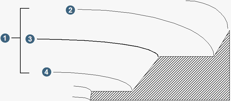
All data are stored as strings. A string is a sequence of three dimensional coordinates delineating some physical feature. As drawn lines in a sketch define essential features, so too do strings. Crests and toes of a mine are strings, as are contours, edges of roads, boundaries of geological zones, and the toe of a stockpile. All points defining a single string are stored in string sequence and assigned a common string number. String numbers are in the range 1 to 32000 inclusive. The following diagram shows part of a bench of an open pit. The bench has three obvious features: its toe, its crest, and the toe of the bench below this bench.
|
|
1. bench 6 2. toe 5 3. crest 6 4. toe 6 |
The following diagram, in plan view, shows the three strings you would normally use to represent those features.
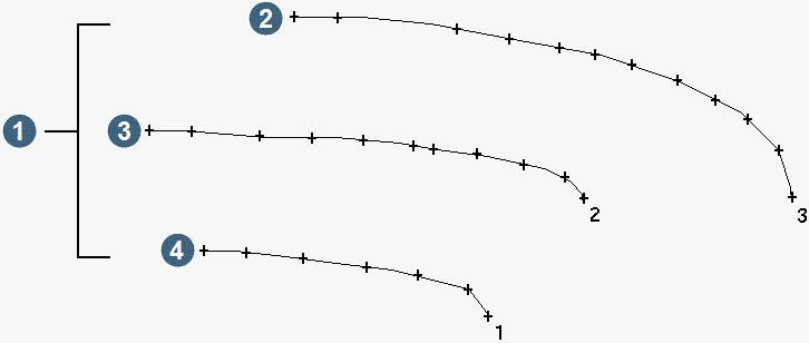
The string number is a numeric identifier of the feature represented by that string. It may have no significance other than to distinguish one string from another, as is often the case in surveying. More commonly, however, it is the code to identify the purpose of a string. For example, the string is a boundary string, or defines a pit slope zone, or waste material.
String Types
Three types of strings are recognised.
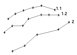
- Open strings, as in a straight or curved line.
If more than one open string exists in a file with the same string number, then these are called open segments of that string and are assigned a segment number.
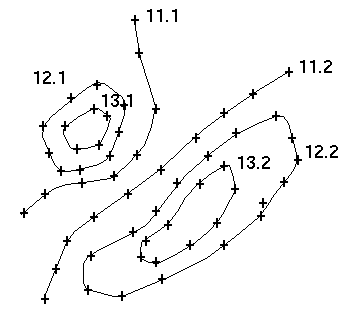
- Closed strings, as in a circle, square or any irregular polygon.
A closed string is one whose first and last co-ordinates are the same.
If more than one closed string exists in a file with the same string number, then these are called closed segments of that string and are assigned a segment number.
This is common in situations where many features, all representing something similar, are logically grouped within a single string identifier, e.g. contours of the same elevation on a topographic map will be assigned the same string number.
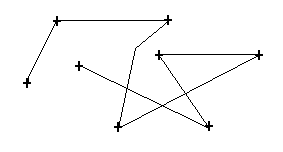
- A spot height string, being a set of random points linked together by a string number, but outlining no particular feature.
The points can be in any order as the actual line joining them does not represent a feature you can see.
Spot height strings are commonly used for recording elevations of points on a surface, or coordinates of bore holes.
Use of String Types
In survey applications it is more common to deal with open strings which define discontinuous features, as are found in open pits, with closed strings being used as boundary strings to constrain a volume computation.
Engineers and geologists tend to be more involved with closed strings, such as bench crests and toes, ore outlines etc. Such closed strings may be assigned a thickness and can therefore be used in calculation of both areas and volumes.
String Descriptions
The ability is provided to be able to assign other 'non-coordinate' information to each point in a string. This data is called the point description. In surveying, this is usually exactly what it is, e.g. a description or name of a control station. When dealing with closed strings, it is more usual that the point description will contain attributes of the feature enclosed by the string, e.g. the concentration and total salinity of a water sample.
The point description may contain sub-fields which can be used to address individually for various purposes. These may include:
- storing assays for multiple elements, e.g. total contaminant calculations
- plotting various description sub-fields for a point at different locations about the point.
The description sub-fields are referred to as D1, D2, D3 up to a maximum of D100. They may be generally referred to as D fields.
The D fields are delimited by commas. In the following example
DESCRIPTION = ``TREE, 1.54, HOUSE''
the sub-fields have the values:
D1 = ``TREE''D2 = ``1.54''D3 = ``HOUSE''
The total length of the description field may not exceed 512 characters regardless of the number of sub-fields.
String Directions
The convention is to plot a string number at the first point of a string. Depending on how a particular string was created, the order of the points will sometimes give a clockwise direction for the string segment and sometimes an anticlockwise one. This direction of segments is important to closed strings when calculating areas and volumes.
If a closed string is defined in a clockwise direction, it is assumed it represents a positive area; that is an area of inclusion.
If it is defined in an anticlockwise direction, it is assumed it represents a negative area; that is, an area of exclusion.
If an anticlockwise closed segment of a string is contained within a clockwise closed segment, the combination is effectively defining the area between the closed segments.
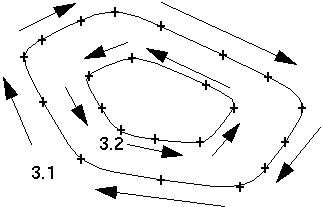
In the previous diagram:
- area of 3.1 = +300
- area of 3.2 = -100
- therefore, area of string 3 = 300 - 100 = 200
String Files
Related strings are stored together in ASCII files called string files, identified by a .str extension. A string file can contain up to 32000 different strings
Another file type produced for storing strings is an observations file, identified by an .obs extension. These files are used for storing raw observed data such as survey co-ordinates downloaded from a data recorder, or when creating strings from foreign data sources such as text files or DXF files.
Observations files are also created by some functions when the resultant strings do not represent the expected model of the real world, e.g. if resultant strings are not all closed when sectioning two DTM's.
The user is expected to recall an observations file into the GRAPHICS module and make the necessary changes before saving as a string file.
Each file is identified by a two part name - the two parts are nominated separately in practice, but they are combined to form a filename acceptable to the computer on which the software is being run. The first part is called the Location code. This is a 1 to 3 alphanumeric character identifier usually chosen to indicate what the strings in the file represent, for example contours, boreholes, or buildings.
The second part is an ID number defining the file as a member of a set of files. This is a 1 to 5 numeric character identifier.
For example, a set of files, each containing salinity readings for an aquifer for the months January, February and March 1990 may be called:
SAL9001
SAL9002
SAL9003
where SAL is the common location code in each case, and the ID numbers are the year/month code of the individual files containing the readings for the aquifer.
If you type a decimal number in an ID, for example 1.65:
- the number is rounded to one decimal place, with 0.05 rounded up (that is, 1.65 rounds to 1.7);
- the one-decimal-place number with the decimal point excluded (that is, 17) will be used for referring to the ID;
- refer to the one-decimal-place number, either with or without the decimal point (that is, either 1.7 or 17), when recalling the file.
String File Structure
Each line in a string file is called a record. The first two records are called the header record and axis record respectively. The header record contains data relating to the whole string file such as the location code, date formed and the purpose.
The axis record contains two sets of co-ordinates identified as string number zero, defining a 3-dimensional axis which is used when taking sections. If no axis has been defined, this record will hold zeros.
The rest of the records in a string file contain points on the strings, with each record having the following structure.
| string number | Y | X | Z | point descriptions |
Each field is delimited by a comma. Records containing zeros in all of the first four fields indicate the end of a segment or string. The final record in the string file with a string number of zero and END in the descriptor field, is the end of file record.
The following example string file(pump1.str) was created using the GROUNDWATER MODELLING module and contains the definitions of three pumping wells. The file contains five description fields, (D1 - D5): borename, Time pump on (days), Time pump off (days), Pumping rate (kl/d) and Pumping bore radius.
pump ,26-Mar-92,pumping
wells ,
|
The second string file (blocks98.str) below shows an example of a string file containing closed segments.
The file was created using the GEOSTATISTICS module and contains regular blocks with a grade calculated using an inverse distance algorithm.
blocks , 1-May-92,Grade
classifications of blocks98.str ,
|
Commonly the Y, X and Z fields hold the northing, easting and elevation, but depending on how the string file was formed, this may not be so. The following shows what co-ordinates will be stored in the Y, X and Z for different sets of data.
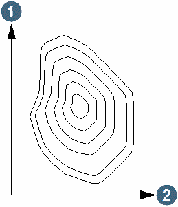
For a plan view of a pit, Y = northing, X = easting, and Z = elevation.
|
1. Y axis = northing 2. X axis = easting |
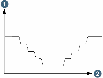
For an east-west section through a pit, Y = elevation, X = easting, and Z = northing.
|
1. Y axis = elevation 2. X axis = easting |
For a north-south section through a pit, Y = elevation, X = northing, and Z = easting.
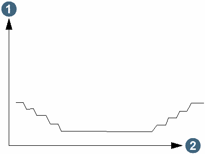
|
1. Y axis = elevation 2. X axis = northing |
For an oblique section through a pit, Y = elevation, X = offset from axis, and Z = distance along axis.
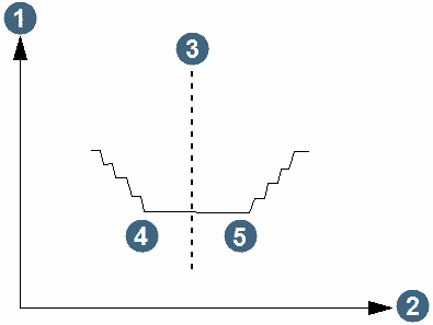
|
1. Y = elevation 2. X = offset from axis 3 axis line 4. negative offset 5. positive offset |
It is easy to swap fields to change the views, or to use the axis co-ordinates to transform the oblique section offset and distance co-ordinates into real world co-ordinates, using the STRING TOOLS module.
Axis
The axis is stored as the second record in a string file. It is used when taking sections through a DTM using the Section DTM function. The sections are taken perpendicular to the axis line.
The axis may be defined using a text editor to add the co-ordinates to the axis record of the string file. If no axis is defined, i.e. the axis length equals zero, then you will be prompted to enter a temporary axis when running the Section DTM function.
The first axis point defines the first section line.
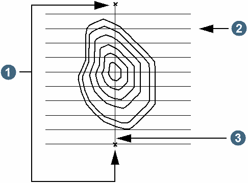
|
1. axis points 2. section lines, that is, sections 3. axis line |
Models
Individual string files, or sets of files, can represent models of physical things. For example, the set of files described earlier are a model of salinity distribution within an aquifer. Similarly, a single string file in which each string is a mid-bench contour of an open pit is a pit model. Models defined on the same set of layers, in either plan or section, can interact each other via the Polygon Intersection function to determine the parts of one model within, or outside, another model. The aquifer and pit models described above can be 'intersected' to create a new model being the `aquifer within the pit'.
Surface topography may be modelled as a single string file in which each string is a different contour, or by a set of files containing one contour per file.
Units of Measurement
All data are treated as unitless. As long as the data units are kept consistent for a project. There is no differentiation between units in metres, feet, ppm's, or ounces, etc.
For example, it you are using imperial measurements such as feet, then you would have to input inches as decimal feet, i.e. 3 inches would be entered as 0.25 feet. If you are using metric measurements such as parts per million, then it would be incorrect to enter data as parts per billion unless they were first converted to ppm's e.g. 10 ppb would be entered as 0.01 ppm.
The only exception is the PLOTTING module when entering the scale of the plot. It then depends on whether the units parameter is set to Imperial or Metric. If it is set to Metric and a scale of 1000 is entered, then it is indicating a scale of 1 mm equals 1000 mm, i.e. 1mm = 1m. If it is set to imperial and a scale of 200 is entered, then it is indicating a scale of 1 inch to 200 feet.
Angles are specified in degrees or grads (centesimal measure) depending upon what has been set up in the defaults.ssi file. If degrees are being used, angles are entered in the form DDD.MMSS e.g. 270.2508 being 270 degrees, 25 minutes and 8 seconds or DDD.DDDD where this represents an angle in decimal degrees where required. If grads are being used, values lie between 0 - 400.
The Worksheet
Handling many files becomes easier with a simple handwritten record. Here's the top few lines of a suitable worksheet in which to record files as you create them.
| Worksheet Date:User's name: Computer:Project: Backup and archive procedure: File specifier Create from Purpose Location ID Extension Filename Extension STK 93308 .dat fld book - Original survey data STK 93308 .not STK99308 .dat Observation report STK 93308 .obs STK99308 .dat Unjoined strings STK 93308 .str STK99308 .dat Joined strings |