


Centre Line Slice
This function allows you to extract slices through a 3DM and/or a block model in the current graphics layer along a segment (centre line).
To run this function: Choose Solids > Solids tools > Section using centre line, or Block model > Sections > Create using centre line string, or...
The centre line along which the slices are taken is defined by selecting two points on a segment. Slices are taken along the segment at a specified spacing and at a specified dip. The first slice is taken at the first selected point and then slices are taken at the specified spacing along the segment until the second selected point is passed.
There are two results which can be produced by the Section using centre line function. The first result is a range of string files which contain the extracted sections in real world or section coordinates as specified. These files are saved to disk. The second result is a file which contains the extracted sections in real world coordinates. These sections can be automatically displayed on screen in a different layer. You may later choose to make this layer the active layer to save this data to a string file. Sections taken from a block model can be placed in a different layer to those extracted from a 3DM.
The segments produced from the Section using centre line function will have the same string number as the object number from which they were extracted. The segments produced may be open or closed segments. Closed objects will always produce closed segments when they are sliced. Open objects may produce open or closed segments when sliced. Closed objects are significant, because the slices generated from slicing a closed object can automatically be used for further processing where closed segments are required.
Segments produced from a block model are identical to extract sections from a block model, with the strings being created dependant on some attribute in the block model. All blocks have their own segment, and a tolerance can be used to slightly shrink the segments.
One reason to slice a 3DM or Block Model along a centre line is to create data for use in Ring Design.
Input
Select the centre line start point
Select a position on a segment to be used for the first slice, another prompt will be displayed.
Select a position on the same segment to be used for the last slice. Selection of the second position will display the SLICE INFORMATION form.
Spacing
Enter the spacing between slices along the centre line.
Number
The number of slices that will be taken between the selected positions given the specified spacing is displayed in this field. Changing this field does not automatically change the spacing between slices. To calculate the slice spacing based on the number of slices, press the Spacing button. For example, if you wish to take five slices between the selected positions (including slices at the two selected positions), enter 5 in this field and press the Spacing button, the calculated spacing will be placed in the Spacing field.
First slice dip
The dip of the first slice (taken through the first selected position).
Last slice dip
The dip of the last slice.
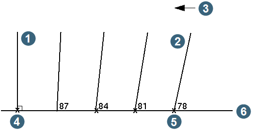
Positive dips cause the slices to be taken at the specified dip towards the first selected point, while negative dips cause the slices to be taken at the specified dip towards the second selected point. Slices taken between the first and last slice have calculated dips based on the first and last slice dips and the number of sections. For example,
First section dip = 90,
Last section dip = 78,
Number of sections = 5,
Section dips = 90 87 84 81 78.
|
1. first section 2. second section 3. positive dip = dipping towards first selected point 4. first selected point 5. second selected point 6. segment (section view) |
Slice dip angles
The default "absolute" mode measures the angle from horizontal whereas the "relative" mode allows us to measure the angle relative to the slope of the centreline. The slices for any portion of the centre line segment that is vertical will only be created in the XY plane regardless of the dip values entered for the slices. The dip is effectively locked at 90 degrees for any slices in a vertical centre line.
Complete the SLICE INFORMATION form and choose Apply to display the EXTRACT SLICES THROUGH OBJECTS form.
Define the objects to be sliced and the new layer name
Object range
Specify the range of objects to be sliced as a valid range identifier. Leaving this field blank causes all objects to be sliced.
Slice layer
Enter a name for the layer to display the sections in real world coordinates. If the layer does not already exist, it will be created. The layer name can be any combination of alphanumeric characters up to 32 characters in length. If this field is left blank, the slices will not be displayed in graphics, and you will have to recall the section files to see the slices.
Slice Block Model?
This field gives you the option of whether or not to slice a block model. No input is allowed in this field, if there is not currently a block model loaded.
BM Slice Layer
Enter a name for the layer to display the sections in real world coordinates. If the layer does not already exist, it will be created. The layer name can be any combination of alphanumeric characters up to 32 characters in length. If this field is left blank, the slices will not be displayed in graphics, and you will have to recall the section files to see the slices.
Define the files to contain the slices
Location
Enter the Location of the file to be created and saved on disk which will contain the slices. If this field is left blank, slices are drawn on the screen but are not saved to a file. This location is for input of the Location for slices of objects only. The Block Model slice location appears on the next form.
ID numbers are
The ID numbers for the string files which are created by this function may represent a simple sequence number or a chainage from the start of the centre line segment. Slices from both 3DMs and Block Models will use these ID numbers. Permissible values for this input field are:
- sequence numbers
- chainages
This will cause the file ID numbers to be created by using a simple sequence starting with the value defined in the Start ID number field and incrementing by 1 for each subsequent slice.
Note that the ID number sequence may contain gaps if no slices are extracted for some of the slice intervals along the centre line. This is to ensure that the numbering sequence is predictable regardless of the objects being sliced.
This will cause the file ID numbers to be created by using the chainage, distance from the start of the centre line segment that is, of the slice.
When using chainages for the file IDs you must also enter an offset value at the Chainage offset prompt. This value is added to the slice chainage to determine the ID number of each file which will be created. Generally this value will be 0.
The chainage offset is especially useful when extracting slices at different times as you can ensure consistency of file IDs even if the centre line segment has different starting positions for different extractions.
Coordinates
Enter the coordinate system for 3DM saved files. Possible values for this field are real world or section. Slices saved in section coordinates have a Z value equal to the chainage along the segment of the section. The coordinates to be used by the block model are found on the next form.
Slicing Block Models
If you are slicing a Block Model, another for will appear. It contains information required to take sections from a block model. It is identical to the Sections form Block Model form.
Messages
After the two points have been selected: Segment distance between selected points:d
If a slice is extracted:
Joining contour segments for level 0.00
			Slice found at distance
			Section written to filename.str
			Slice found at distance distance
If no slice is extracted:
No slice found at distance distance
Result
The string files containing the slices are written to disk. Slices in real world coordinates are automatically displayed on the screen in the specified layer. The message window confirms the processing.
If the Coordinates field specified real world coordinates, the YXZ fields of each point will contain real world coordinates and the description fields (D1, D2 and D3) will contain section coordinates.
If the Coordinates field specified section coordinates, the YXZ fields will contain section coordinates and the description fields will contain real world coordinates.
The fourth description field of each point in the slice(s) contains the name of the object from which it was taken, if the object had been named prior to slice extraction.
Warning
If no slices were extracted: No slices extracted from the model
This could be due to:
- incorrectly specified object numbers
- no objects being in the active layer