


Clip DTM with string
You can use this function to trim a DTM to a boundary before you use it in further processing. For example, to create pillars in the backs of an underground development.
To run this function: Choose Surfaces > Clip or intersect DTMs > Clip DTM with string, or...
The outer boundary segment must be clockwise and can contain any number of anticlockwise and clockwise segments. The direction of the nested segments (clockwise or anticlockwise) is not important.
Imagine that you are viewing a surface along the normal to the plane used during surface creation (that is, looking directly at the plane), the rules for clipping are:
- For a single segment string, "inside" the segment refers to triangles physically inside the segment.
- For a string with a single level of nested segments, "inside" refers to triangles physically inside the outermost segment but outside any inner segments.
- Multiple levels of nesting are handled by alternating "inside" and "outside" for each level of nesting. For example, if the black lines are segments of a string, the red areas are considered "inside" the string and the white areas are "outside":
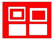
Because you can use this function to produce donut type shapes, it is recommended that DTMs created by this function are not used by DTM functions that rely on the DTM having no holes. For example;
- SECTION DTM
- DTM BOUNDARY
- DTM VOLUMES
- STRINGS OVER DTM
You can use the clipped DTMs from this function, as the top and bottom seam of a deposit to create 3DMs using the solids modelling functions. You use the boundary strings of the clipped DTMs to stitch the two clipped portions together. The result of GRAPHICALLY CLIP DTM includes a string for the clipping boundary, which is the boundary string and any new points that were created when clipping the triangles against the boundary.
You are prompted to select the trisolation to clip, and then the boundary string to clip with. After you have selected the trisolation and string in Graphics, the Apply a boundary to a DTM form is displayed.
Fields on the Apply a boundary to a DTM form
| Field | Description |
|---|---|
| Selected DTM | |
| DTM name | Display only. The name of the DTM you selected in Graphics. |
| Object ID | Display only. The object number of the DTM you selected in Graphics. |
| Trisolation ID | Display only. The trisolation number of the DTM you selected in Graphics. |
| Selected boundary string | |
| Layer name | Display only. The name of the string file you selected in Graphics. |
| String number | Display only. The string number of the boundary string you selected in Graphics. |
| Define results | |
| Retain triangles |
|
| New boundary layer | The name and location to save the new boundary layer. |
Output
The clipped DTM, including the new boundary string that contains the new points created while splitting the triangles, is saved.
When using a DTM and boundary string that were created on a non-horizontal plane, the process is:
- The DTM and input string data are transformed so that the plane is horizontal.
- The overlaying process proceeds as for a horizontal plane DTM.
- The results are back-transformed to sit on the original DTM location.
The X, Y position of points from the string file that lie within the boundary of the DTM are located accurately within a given triangle. The points do not have to coincide with the triangle apices. The operation chosen is performed by interpolation if the X, Y positions vary.
Interpolation is possible because each triangle represents a continuous plane of linear interpolated points between the three triangle apices. If points lie outside the boundary of the DTM, then a degree of extrapolation occurs. Extrapolation is performed by locating the nearest triangle centroid to the point, extrapolating the triangle plane to define a gradient, and then interpolating a new value based on the linear gradient.
Troubleshooting
| Field | Description |
|---|---|
Boundary point is outside DTM
					Y=yyy X=xxx
|
A point on the boundary string is outside the DTM at the coordinates shown. |