


Ramps
Each of the functions relating to ramps, which expand or contract segments, also create ramps for both all cut ramps and circular ramps.
All cut ramps (at least when designing an excavation, they are all fill ramps when designing a dump), require both a starting position in the segment which is to contain the ramp, and a segment which represents the path which the ramp will follow as it progresses from one level to the next. The elevations of the points in the centre line segment are irrelevant as the elevations of the ramp points are determined as the segments are expanded/contracted.
Circular ramps only require a starting position in the segment containing the ramp. The path of the ramp is determined as the segment is expanded/contracted with the ramp spiralling around the segment as the design progresses from one level to the next.
In addition to the type of ramp, the ramp starting position, and of course the centre line for all cut ramps, the ramps are further defined by their physical characteristics such as width and gradient.
There is no limit to the number of ramps which can be associated with a segment nor to the mix of circular and all cut ramps which can be associated with a segment. Care should be taken to ensure that ramps don’t unduly impact on each other as this is likely to make the ramp geometry behave in an undesirable manner, for example, a circular ramp progressing around the end of an all cut ramp is likely to give strange results.
Considerations for ramp design
In preparation for designing ramps you must prepare an appropriate starting position for the ramp. An appropriate starting position will ensure good ramp design while an inappropriate starting position is likely to produce undesirable ramp geometry at the start of the ramp at the very least.
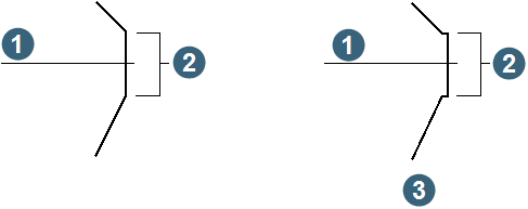
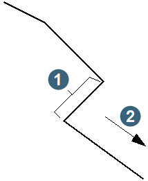
For both all cut and circular ramps, the starting position of the ramp must be represented by 2 points which are immediately adjacent to each other on the segment which is being used. These points should be separated by a distance which is approximately equal to the width of the ramp which will be created. Typical configurations of these points for both types of ramps are shown below.
When an all cut ramp is defined, a small adjustment is made to the segment outline to give an appropriate starting position for the ramp. This starting position is created by inserting two new points in the segment and extending the segment along the direction defined by the ramp centre line segment for a distance of 1 unit (that is metres/feet). The following diagram shows an example of how the segment shape is altered when an all cut segment is defined for a segment.
|
1. ramp centre line 2. ramp starting points 3. geometry after adjustments have been made |
Typical starting position for a circular ramp
|
1. ramp starting points 2. direction of ramp advance |