


New rig
The ADD RIG function allows the addition of a new rig definition to the list of rigs available in Ring Design. The definition of a rig requires entry of information about a rig's dimensions and limitations into a form. The string representing the rig is then created by the Ring Design functions when the rig is selected for use.
To run this function: Choose Design > Ring design > Setup > New rig, or...
Rig name
The name of the rig.
Rig width
The maximum width of the rig. This is used to ensure:
- that the selected opening will accommodate the rig
- that the drill mast is never positioned wider than the rig allows, in the case where the mast cannot be moved further than the rig width (eg a pivot which is fixed on the rig).
Max hole length
The maximum hole length that a rig can drill. This is used to prevent the design of holes which are deeper than a rig can drill.
Rod length
The length of each rod for the rig. This is used when reporting the number of rods to drill for a hole in DRILLING Report.
Carousel:
|
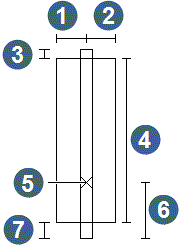
1. left width 2. right width 3. bit distance 4. carousel length 5. pivot 6. feed - pivot distance 7. feed distance |
| Facing from the rig towards the mast | |
The carousel measurements required to define the rig are illustrated above.
length
The length of the carousel.
left width
The width of the carousel to the left of the pivot point (facing towards the mast from the rig).
right width
The width of the carousel to the right of the pivot point (facing towards the mast from the rig).
bit distance
The length of the mast from the top of the carousel to the bit.
feed distance
The length of the mast from the bottom of the carousel to the 'feed' end of the mast.
feed - pivot distance
The length of the mast from the pivot point to the 'feed' end of the mast.
pivot offset
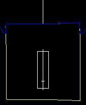
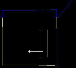
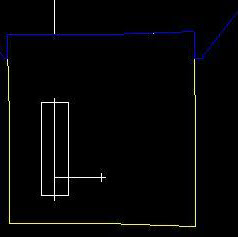
This value allows you to define an offset distance from the pivot to the mast. A positive offset will mean the mast is positioned to the right of the pivot as you look towards the section from the specified direction. A negative offset will mean the mast is positioned to the left of the pivot as you look towards the section from the specified direction.
The three diagrams below respectively illustrate the effects of a zero pivot offset value, a positive pivot offset value, and a negative pivot offset value:
Zero pivot offset
Positive pivot offset
Negative pivot offset
Pivot:
min height
The minimum height of the pivot from the ground. This is used by the MOVE MAST functions to ensure that the pivot point is not positioned lower than the rig is capable of.
max height
The minimum height of the pivot from the ground. This is used by the MOVE MAST functions to ensure that the pivot point is not positioned higher than the rig is capable of.
lateral
The total extent of lateral movement of the mast. This is used to ensure that the drill mast is never positioned wider than the rig allows, in the case where this value is less than the specified rig width.
Angle definition method
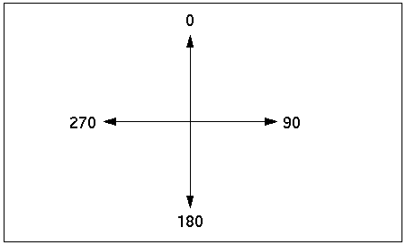
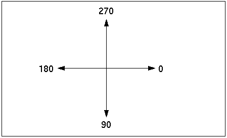
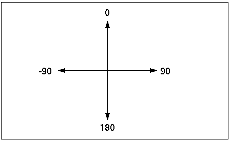
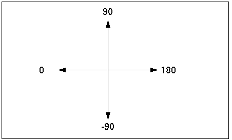
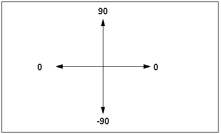
The method to use when defining angles in the plane for this rig. Valid entries for this field are 360 degrees, 180 degrees or dip and dip direction. For 180 degrees or 360 degrees, clockwise angles are positive, while anticlockwise angles are negative (facing away from the rig towards the mast). Dip and dip direction reports the 'dip' of the hole in the ring plane and the direction of the dip (N, S, E or W) as shown below, 'up-holes' are given positive dips.
origin
The direction to use for an angle of 0 degrees. Valid entries are up, down, left or right. These directions assume you are facing from the rig towards the mast.
The diagrams below shows the result of some combinations of angle definition method and origin.
360 degrees, origin = up
360 degrees, origin = right
180 degrees, origin = up
180 degrees, origin = left
dip and dip direction
Enter values for the fields on the form and choose Apply to add the new rig definition to the list of rigs for the current session. To save the new rig definition for future sessions, choose Save Defaults from the RING DESIGN menu.