Extend collar points
You can use this function to change the length of individual blast holes, for example to make the toe of a blast hole extend to a bench level represented by a surface, or to crop the blast hole to that surface.
Prerequisites: For this function to be useful, at least one blast hole must be displayed in Graphics as a string.
To run this function: Choose Design > Blast design > Blast design > Extend collar points, or...
Fields on the Bottom of hole parameters form
| Field | Description |
|---|---|
| Toe position method |
|
| Hole length | The absolute hole length for the blast hole. This field is visible when you select the Set Length method. |
| Elevation | The absolute elevation of the bottom of the blast hole. This field is visible when you select the Set Elevation method. |
| Layer name | The layer that contains the surface that the toe of the blast hole will intersect. This field is visible when you select the DTM layer method. |
| Location | The name of the DTM file that holds the surface where the blast hole stops. This field is visible when you select the DTM file method. |
| ID | The ID of the DTM file that holds the surface where the blast hole stops. This field is visible when you select the DTM file method. |
| Object ID | The Object ID of the surface where the blast hole finishes. This field is visible when you select the DTM layer or DTM file method. |
| Trisolation ID | The Trisolation ID of the surface where the blast hole finishes. This field is visible when you select the DTM layer or DTM file method. |
| Make Visible? | Determines whether the lower DTM is displayed in Graphics. |
| Segment offset | The distance from the segment to offset the blast hole. |
| Fix value |
If you specify a Segment offset, either the offset distance or the bearing must be slightly different from the value you specified.
|
| Subdrill distance |
The amount of additional length to add to the blast hole to account for subdrill. |
| Hole bearing | The angle of orientation of the blast hole in plan view. A Hole bearing of 0 is north. |
| Hole dip | The angle of orientation of the blast hole in section view. A Hole dip of 0 is directly into the ground. |
| Hole diameter | The diameter of the blast hole. Hole diameter is a property of each point in the blast hole. |
Output
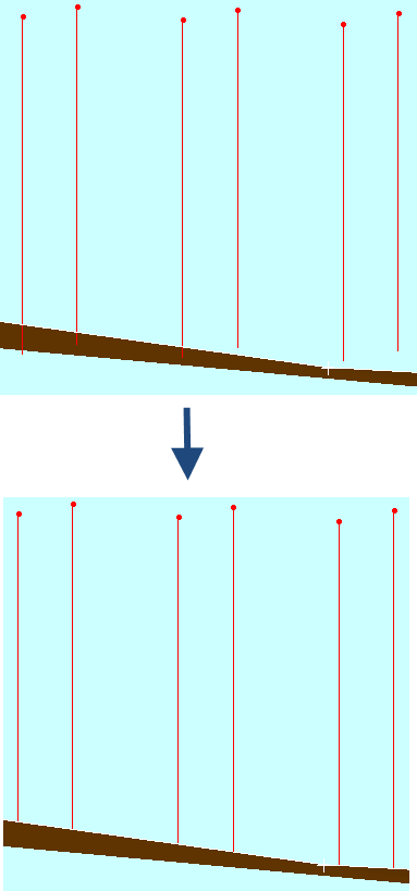
The holes you selected are extended or reduced to the length you specified.
The following image shows an example where Toe position method is set to DTM file.