


Create blast boundary string
This function is useful for creating an approximate outline of the blast so that you can see whether the blast would extend into a face or any other area you want to remain unaffected by the blast. The blast outline is determined by a blast destruction cone for each drill hole, which is created from the explosive blast angle. The blast cone for each hole is created and then these cones are joined together to create a blast boundary string. The true blast outline is used to develop a blast solid.
To run this function: Choose Design > Blast design > Blast design > Create blast boundary string, or...
The blast boundary string is created using either blast holes from the graphics layer "blast hole layer" or from the blast holes loaded in the drill hole database. The software first checks for the "blast hole layer", if that does not exist then the drill hole database will be used for creating the blast boundary.
In a properly designed blast, the blast cones when projected to the bench level from which the holes have been drilled should overlap such that there is no region within the blast boundary that is not included in at least one blast cone. In that case the layer defined for the blast boundary string will have only one string. If the blast boundary layer has more than one segment the blast boundary will be the outermost string with other closed segments defining the regions where the rock will not be effectively blasted. The software will display suitable warning messages if this situation exists.
The trisolations are created if the Create cones check box is ticked. The image below shows an example of the blast cone trisolations.
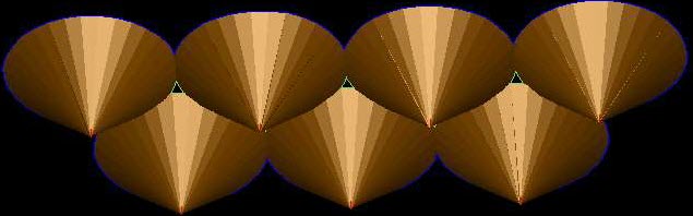
 Note: To display the blast cones, you must run the DRAW OBJECTS function.
Fields on the True blast boundary form
Define output layer
Enter the name of the layer that is to be created. The blast boundary string will be created in this layer.
Pattern identifier
This field is active only if you are using the database for creating the blast boundary, otherwise it is inactive. Choose the pattern identifier from the combo box to be used for creating the blast boundary.
When you use the graphics layer "blast hole layer" for creating a blast boundary all the blast holes from "blast hole layer" will be used for creating the blast boundary.
String number
Enter the string number to define the blast boundary string that will be created using this function. The same string number will be assigned to the strings created at the toe of the blast cones, if the blast cones are to be created.
Create cones
Tick this box for creating the blast cones for each blast hole. These cones will be created in a separate layer called "cones".
Note: To display the blast cones, you must run the DRAW OBJECTS function.
Overwrite Cone angle
Tick this box for displaying the field for cone angle. The value entered in that field will be used for creating the blast boundary/cones and the value present in the blast defaults will be ignored.
Untick this box for creating the blast boundary/cones using the cone angle from the blast defaults. If the cone angle is not defined in the blast defaults, then an fixed angle of 45 deg will be used for creating the blast boundary/cones.
Cone angle
Enter the blast cone angle i.e explosive blast angle to be used for creating the blast boundary/cones. The cone starts from the bottom of the hole (including the sub-drill) and is measured from the horizontal plane. Example a cone of 85 deg gives a long narrow cone and a cone of 20 deg gives a wide cone
Arc distance
Enter the arc distance required between the points on the circumference to create the blast boundary string. The smaller the distance entered, the better the segment will approximate a smooth curve, but more points will be created. An example value is 1.0.
Collar elevation
Define how the elevations of the top of the blast cone for each blast hole will be determined. The apex of the blast cone is at the toe of the blast hole. The blast cones are extended to the surface using the defined elevations. For setting the collar elevation you need to select one of the choices from the combo box.
Valid choices are :
- Fixed
- DTM layer
- DTM file
If Fixed is selected, you will be prompted to enter an elevation (Z value). The elevations of the blast boundary will be set to this value.
If you select DTM layer, you will be prompted to enter the name of another existing layer which contains a DTM. This layer must contain a DTM that is numbered object 1, trisolation 1. This DTM must be a DTM surface and not a 3D solid model. In other words, the DTM must have been created using the function CREATE DTM, and not with any of the solids modelling tools. The collar elevation of each hole will be set to the elevation of the DTM where the hole intersects the DTM.
If you select DTM file, you will be prompted to enter the name of an existing DTM file, and whether or not you wish for the DTM to be displayed. This DTM must be numbered object 1, trisolation 1. This DTM file must be a DTM surface and not a 3D solid model. In other words, the DTM must have been created using the function CREATE DTM, and not with any of the solids modeling tools. The collar elevation of each hole will be set to the elevation of the DTM where the hole intersects the DTM.
Errors
When you run this function, the software checks whether the graphics layer "blast hole layer" exists, if that layer does not exist then it checks for the drill hole database for creating the blast boundary. When both of these do not exist then the following error message will be displayed.
No drillholes in the Blast hole layer. Design some blast holes in the blast hole layer / Load the blast hole database for generating the blast boundary.
When the layer containing the blast boundary string contains more than one string, then the following error message is displayed.
The blast boundary string contains more than one segment. This means that the blast comes when projected to the bench level from which the holes have been drilled do not overlap the entire region within the blast boundary. This is generally the result of a flawed blast design. The outermost segment is the blast boundary and the inner segments define the regions where the rock may not be effectively blasted.
When the DTM extents are not large enough to intersect all cone projections to the DTM surface, then the following error message is displayed.
The DTM extents are not large enough to intersect all cone projections to the DTM surface. Please increase the extents of the DTM and try again.